
Hi all
My name is Carlos Llanos and reading I found portalpez.com domain automate an aquarium with arduino but that project (Excellent project) is obsolete and end of the post to post ferduino recommended. Now I have a question: is there some post such as the portalpez http://www.portalpez.com/1-vf7-vt51459. ... sc&start=0 in a step by step summary ?.
Thank you
Excuse for my English, I used Google translate to for this.
Hola a todos
Mi nombre es Carlos Llanos y leyendo del dominio portalpez.com encontré como automatizar un acuario con arduino pero ese proyecto (Excelente proyecto) ha quedado obsoleto y al final del post recomendaban al post de ferduino. Ahora tengo una pregunta: ¿existe algun post tal como el del portalpez http://www.portalpez.com/1-vf7-vt51459. ... sc&start=0 en resumen un paso a paso?.
Gracias
Perdonen mi ingles, usé translate de Google para esto.
Forum ‹ Members section ‹ DIY Ferduino controller ‹ Step By Step for Dummies?
Thanx Fernando
I will be reading this post, I hope come to good port.
I have a question: These components are used for freshwater aquariums ?, no plan to have some version of your hardware simpler ?, such as sensor ph only two circuits for temperature, etc.
The R2 is a resistor pull-down, check it : http://en.wikipedia.org/wiki/Pull-up_resistor
"Fonte" in english is power supply, you need connect the negative (GND or ground) from power supply and Arduino on this circuit.
The positive goes directly to the LED.
hi Fer
Sorry to bother you, I'm a bit ignorant on this issue, I have a doubt resistance, for example R2, R4, one leg is not connected to anything, and the GND-Fonte-Arduino-E, also did not see anything connected if I do not understand. That's OK?
Ooh, thanx. Again, searching parts for my project, you recommend me this ITDB02 ARDUINO MEGA SHIELD V1.1 KIT http://imall.iteadstudio.com/im120717001.htmlbut this shield ITDB02 ARDUINO MEGA SHIELD http://imall.iteadstudio.com/im120417024.html , Is this last component can run me? only thing is that this component don't have rtc, I believe it. or this http://www.ebay.com/itm/400652791828, which one I must to choice?
Hi!
Gerardo how is going your project?
It would be interesting if you post here a step by step according to what you would like of have found on forum.
Best regards.
Step By Step for Dummies?
17 posts
• Page 1 of 1
Post Number:#1
 Sat Aug 09, 2014 12:00 am
Posts: 16
Topics: 3 Solve rating: 0 Joined: Fri Aug 08, 2014 11:17 pm Topics: 3
Age: 52 Location: Barranquilla Gender: 
National Flag:

Post Number:#2
Sat Aug 09, 2014 11:49 am


Posts: 1699
Topics: 38 Images: 301 Solve rating: 233 Joined: Mon Mar 03, 2014 5:59 pm Topics: 38
Age: 41 Location: São Paulo Gender: National Flag:

Hi!
Welcome Carlos!
You can find all circuits, part list and step by step to install the code on links below.
How to install Ferduino code
Part list
Circuits
Code for tests
If you have any question can post here.
Best regards.
Welcome Carlos!
You can find all circuits, part list and step by step to install the code on links below.
How to install Ferduino code
Part list
Circuits
Code for tests
If you have any question can post here.
Best regards.
Post your doubts on forum because it can help another user too. Just PM me for support if it's absolutely necessary.
Post Number:#3
Sat Aug 09, 2014 12:10 pm
Posts: 16
Topics: 3 Solve rating: 0 Joined: Fri Aug 08, 2014 11:17 pm Topics: 3
Age: 52 Location: Barranquilla Gender: National Flag:
Hi!
Welcome Carlos!
You can find all circuits, part list and step by step to install the code on links below.
How to install Ferduino code
Part list
Circuits
Code for tests
If you have any question can post here.
Best regards.
Welcome Carlos!
You can find all circuits, part list and step by step to install the code on links below.
How to install Ferduino code
Part list
Circuits
Code for tests
If you have any question can post here.
Best regards.
Thanx Fernando
I will be reading this post, I hope come to good port.
I have a question: These components are used for freshwater aquariums ?, no plan to have some version of your hardware simpler ?, such as sensor ph only two circuits for temperature, etc.
Post Number:#4
Sat Aug 09, 2014 12:28 pm
Posts: 1699
Topics: 38 Images: 301 Solve rating: 233 Joined: Mon Mar 03, 2014 5:59 pm Topics: 38
Age: 41 Location: São Paulo Gender: National Flag:
This components can be used to freshwater or saltwater. The difference is that to freshwater you no need of circuits for ORP and EC.
I'll not make another version, this code can be used to any type of tank.
If you no need of two PH sensors only no connect the second circuit, it no will interfere on controller.
Here have a good example of controller for freshwater.
I'll not make another version, this code can be used to any type of tank.
If you no need of two PH sensors only no connect the second circuit, it no will interfere on controller.
Here have a good example of controller for freshwater.
Post your doubts on forum because it can help another user too. Just PM me for support if it's absolutely necessary.
Post Number:#5
Sat Aug 09, 2014 1:42 pm
Posts: 16
Topics: 3 Solve rating: 0 Joined: Fri Aug 08, 2014 11:17 pm Topics: 3
Age: 52 Location: Barranquilla Gender: National Flag:
Hi there
One question: If I'm just going to have LED lights, temperature control fans need all the elements?
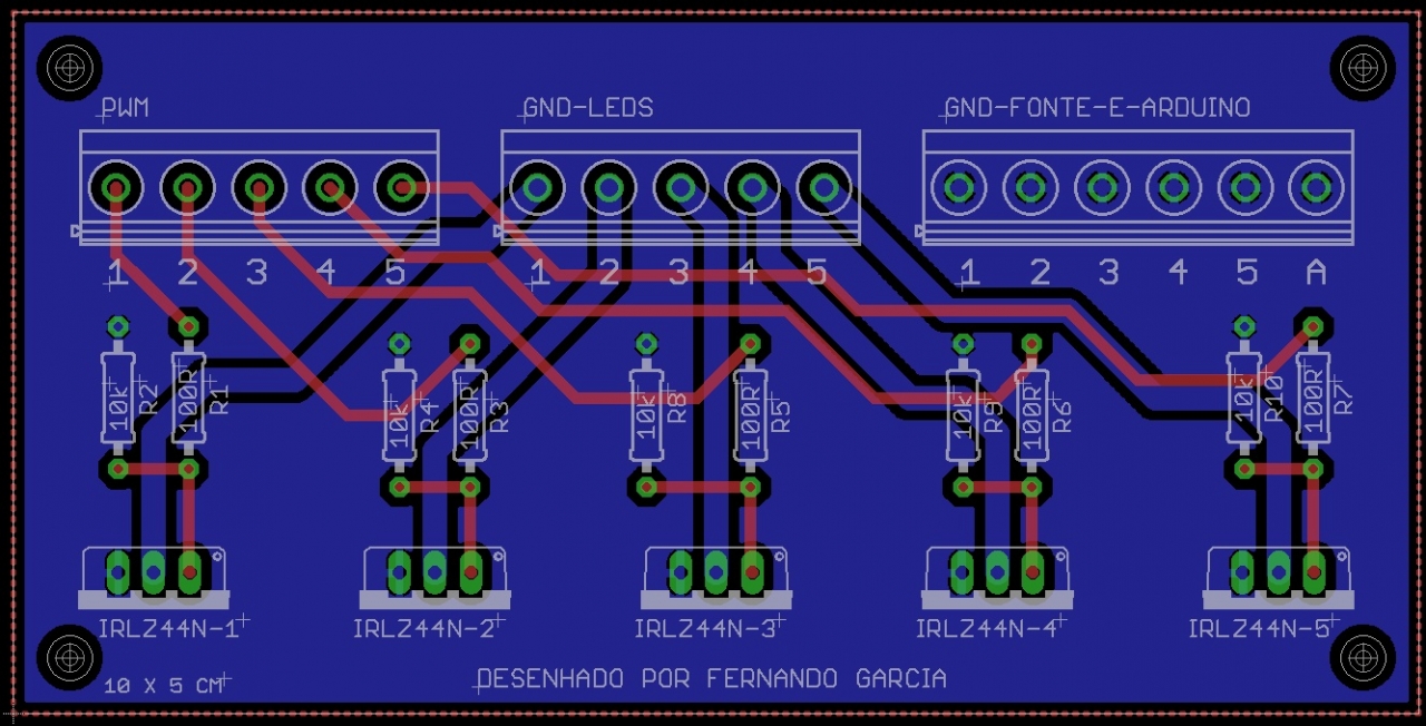
Another question: In this image gallery/image.php?album_id=11&image_id=70, what is the function the R2 resistors and the GND-FONTE-E-ARDUINO?
One question: If I'm just going to have LED lights, temperature control fans need all the elements?
Another question: In this image gallery/image.php?album_id=11&image_id=70, what is the function the R2 resistors and the GND-FONTE-E-ARDUINO?
Last edited by Carlos Llanos on Sat Aug 09, 2014 2:11 pm, edited 1 time in total.
Post Number:#6
Sat Aug 09, 2014 1:48 pm
Posts: 1699
Topics: 38 Images: 301 Solve rating: 233 Joined: Mon Mar 03, 2014 5:59 pm Topics: 38
Age: 41 Location: São Paulo Gender: National Flag:
No, you need:
Arduino mega 2560;
TFT touch 400 x 240;
TFT shield with RTC;
Temperature sensors (ds18b20);
Prototype shield or screw shield.
-------------------------------- Last edited Sat Aug 09, 2014 1:57 pm --------------------------------
If you not want buy a prototype shield or screw shield, connect the wires on this way:
Post your doubts on forum because it can help another user too. Just PM me for support if it's absolutely necessary.
Post Number:#7
Sat Aug 09, 2014 3:29 pm
Posts: 16
Topics: 3 Solve rating: 0 Joined: Fri Aug 08, 2014 11:17 pm Topics: 3
Age: 52 Location: Barranquilla Gender: National Flag:
Hi
Another question: In this image gallery/image.php?album_id=11&image_id=70, what is the function the R2 resistors and the GND-FONTE-E-ARDUINO?
Another question: In this image gallery/image.php?album_id=11&image_id=70, what is the function the R2 resistors and the GND-FONTE-E-ARDUINO?
Post Number:#8
Sat Aug 09, 2014 3:47 pm
Posts: 1699
Topics: 38 Images: 301 Solve rating: 233 Joined: Mon Mar 03, 2014 5:59 pm Topics: 38
Age: 41 Location: São Paulo Gender: National Flag:
The R2 is a resistor pull-down, check it : http://en.wikipedia.org/wiki/Pull-up_resistor
"Fonte" in english is power supply, you need connect the negative (GND or ground) from power supply and Arduino on this circuit.
The positive goes directly to the LED.
Post your doubts on forum because it can help another user too. Just PM me for support if it's absolutely necessary.
Post Number:#9
Sat Aug 09, 2014 4:27 pm
Posts: 16
Topics: 3 Solve rating: 0 Joined: Fri Aug 08, 2014 11:17 pm Topics: 3
Age: 52 Location: Barranquilla Gender: National Flag:
Image: http://ferduino.com/forum/gallery/image.php?album_id=11&image_id=70
The R2 is a resistor pull-down, check it : http://en.wikipedia.org/wiki/Pull-up_resistor
"Fonte" in english is power supply, you need connect the negative (GND or ground) from power supply and Arduino on this circuit.
The positive goes directly to the LED.
The R2 is a resistor pull-down, check it : http://en.wikipedia.org/wiki/Pull-up_resistor
"Fonte" in english is power supply, you need connect the negative (GND or ground) from power supply and Arduino on this circuit.
The positive goes directly to the LED.
hi Fer
Sorry to bother you, I'm a bit ignorant on this issue, I have a doubt resistance, for example R2, R4, one leg is not connected to anything, and the GND-Fonte-Arduino-E, also did not see anything connected if I do not understand. That's OK?
Post Number:#10
Sat Aug 09, 2014 4:49 pm
Posts: 1699
Topics: 38 Images: 301 Solve rating: 233 Joined: Mon Mar 03, 2014 5:59 pm Topics: 38
Age: 41 Location: São Paulo Gender: National Flag:
No problem.
Look this image.
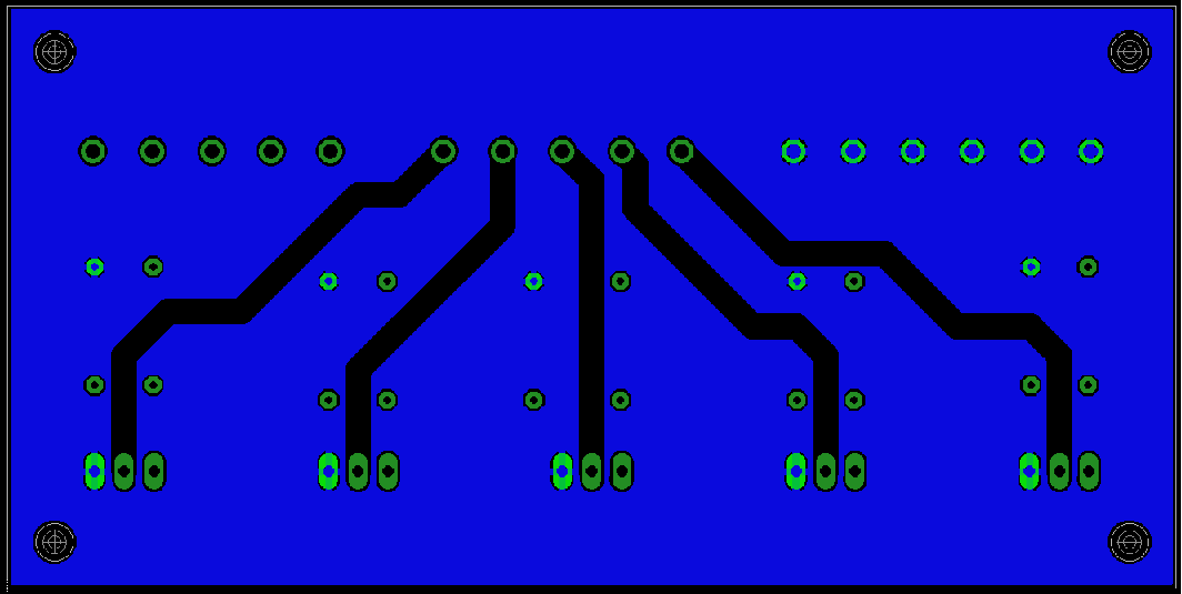
All this area is a signal of ground, all points highlighted are connected to it.
Look this image.
All this area is a signal of ground, all points highlighted are connected to it.
Post your doubts on forum because it can help another user too. Just PM me for support if it's absolutely necessary.
Post Number:#11
Sat Aug 09, 2014 5:38 pm
Posts: 16
Topics: 3 Solve rating: 0 Joined: Fri Aug 08, 2014 11:17 pm Topics: 3
Age: 52 Location: Barranquilla Gender: National Flag:
No problem.
Look this image.
Image: http://www.ferduino.com/forum/gallery/image.php?album_id=11&image_id=111
All this area is a signal of ground, all points highlighted are connected to it.
Look this image.
Image: http://www.ferduino.com/forum/gallery/image.php?album_id=11&image_id=111
All this area is a signal of ground, all points highlighted are connected to it.
Ooh, thanx. Again, searching parts for my project, you recommend me this ITDB02 ARDUINO MEGA SHIELD V1.1 KIT http://imall.iteadstudio.com/im120717001.htmlbut this shield ITDB02 ARDUINO MEGA SHIELD http://imall.iteadstudio.com/im120417024.html , Is this last component can run me? only thing is that this component don't have rtc, I believe it. or this http://www.ebay.com/itm/400652791828, which one I must to choice?
Post Number:#12
Sat Aug 09, 2014 5:59 pm
Posts: 1699
Topics: 38 Images: 301 Solve rating: 233 Joined: Mon Mar 03, 2014 5:59 pm Topics: 38
Age: 41 Location: São Paulo Gender: National Flag:
You can buy this TFT shield but, first see this topic to not buy a RTC wrong.
This prototype shield is different of this:

This prototype shield is different of this:
Post your doubts on forum because it can help another user too. Just PM me for support if it's absolutely necessary.
Post Number:#13
Tue Sep 16, 2014 7:56 am
Posts: 3
Solve rating: 0 Joined: Wed Aug 13, 2014 8:30 am Age: 47 Gender: 
National Flag:

Hi all 
Does anyone have a step by step with pictures and what connects to what???
Does anyone have a step by step with pictures and what connects to what???
Post Number:#14
Tue Sep 16, 2014 10:11 am
Posts: 1699
Topics: 38 Images: 301 Solve rating: 233 Joined: Mon Mar 03, 2014 5:59 pm Topics: 38
Age: 41 Location: São Paulo Gender: National Flag:
Post your doubts on forum because it can help another user too. Just PM me for support if it's absolutely necessary.
Post Number:#15
Tue Sep 16, 2014 1:43 pm
Posts: 3
Solve rating: 0 Joined: Wed Aug 13, 2014 8:30 am Age: 47 Gender: National Flag:
Hummmmmm...
Ok, THX, i don’t understand much of electronics and connections but I WILL TRY, AND I WILL SUCCEED

Ok, THX, i don’t understand much of electronics and connections but I WILL TRY, AND I WILL SUCCEED
Post Number:#16
Mon Dec 08, 2014 9:49 am
Posts: 1699
Topics: 38 Images: 301 Solve rating: 233 Joined: Mon Mar 03, 2014 5:59 pm Topics: 38
Age: 41 Location: São Paulo Gender: National Flag:
Hummmmmm...
Ok, THX, i don’t understand much of electronics and connections but I WILL TRY, AND I WILL SUCCEED
Ok, THX, i don’t understand much of electronics and connections but I WILL TRY, AND I WILL SUCCEED
Hi!
Gerardo how is going your project?
It would be interesting if you post here a step by step according to what you would like of have found on forum.
Best regards.
Post your doubts on forum because it can help another user too. Just PM me for support if it's absolutely necessary.
Post Number:#17
Sun Oct 18, 2015 1:29 am


Posts: 275
Topics: 6 Images: 46 Solve rating: 0 Joined: Mon Sep 08, 2014 1:35 am Topics: 6
Age: 44 Location: Byers Gender: National Flag:

so following Fernando's request I am going to start from scratch thread here, I will work on each component as I get time and post updates regularly. So far I have most of what I need and I think I will start by building the stack. I will post some pictures soon, I would like any others to add their experiences as well this help take some of the questions that Fernando gets all the time and make a little brake for him. Thank all and lets have some fun.
Happy reefing to all.
Christopher Kindig
Christopher Kindig
17 posts
• Page 1 of 1
Return to DIY Ferduino controller
Who is online
Users viewing this topic: No registered users and 1 guest