Forum ‹ Members section ‹ Show your controller ‹ New build.
New build.
Post Number:#101
 Wed Jan 21, 2015 3:13 am


Posts: 274
Topics: 6 Images: 46 Solve rating: 0 Joined: Mon Sep 08, 2014 1:35 am Topics: 6
Age: 42 Location: Aurora Gender: 
National Flag:

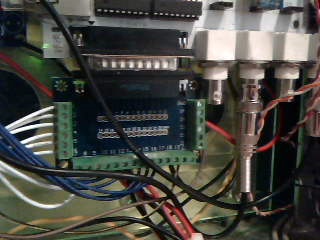
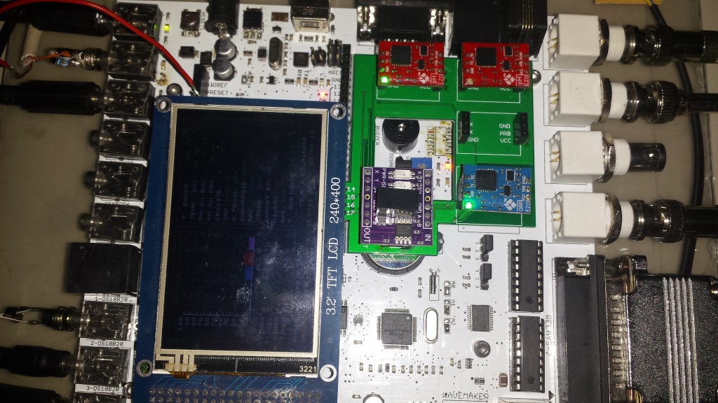
Ok so I finally got around to reworking my cable for the display and it works correctly, next to get network issue straight and set up dosing pumps. I have 4 now I will order 2 more to set as future use total of 6 heads. Will Ferduino run 12 volt dosing pump or is there something specific I have to do?
Happy reefing to all.
Christopher Kindig
Christopher Kindig
Post Number:#102
Wed Jan 21, 2015 8:58 am


Posts: 1699
Topics: 38 Images: 301 Solve rating: 233 Joined: Mon Mar 03, 2014 5:59 pm Topics: 38
Age: 39 Location: São Paulo Gender: National Flag:

Hi!
If the board is powered with 12V you can use this wiring.
Otherwise will get 12V from PC power supply as I told on first post.
Best regards.
If the board is powered with 12V you can use this wiring.
Otherwise will get 12V from PC power supply as I told on first post.
Best regards.
Post your doubts on forum because it can help another user too. Just PM me for support if it's absolutely necessary.
Post Number:#103
Wed Jan 21, 2015 10:09 am
Posts: 274
Topics: 6 Images: 46 Solve rating: 0 Joined: Mon Sep 08, 2014 1:35 am Topics: 6
Age: 42 Location: Aurora Gender: National Flag:
Hi Fernando!
So I will connect 12 volt to + motor then negative is switched on and off through Ferduino? As sown in the schematic for 12 volt.
So I will connect 12 volt to + motor then negative is switched on and off through Ferduino? As sown in the schematic for 12 volt.
Happy reefing to all.
Christopher Kindig
Christopher Kindig
Post Number:#104
Wed Jan 21, 2015 10:41 am
Posts: 1699
Topics: 38 Images: 301 Solve rating: 233 Joined: Mon Mar 03, 2014 5:59 pm Topics: 38
Age: 39 Location: São Paulo Gender: National Flag:
Yes, make sure that GND of Power supply and Ferduino M. are common.
Post your doubts on forum because it can help another user too. Just PM me for support if it's absolutely necessary.
Post Number:#105
Thu Jan 22, 2015 9:27 pm
Posts: 274
Topics: 6 Images: 46 Solve rating: 0 Joined: Mon Sep 08, 2014 1:35 am Topics: 6
Age: 42 Location: Aurora Gender: National Flag:
do I use the ground from RJ45 jack?
Happy reefing to all.
Christopher Kindig
Christopher Kindig
Post Number:#106
Thu Jan 22, 2015 9:40 pm
Posts: 1699
Topics: 38 Images: 301 Solve rating: 233 Joined: Mon Mar 03, 2014 5:59 pm Topics: 38
Age: 39 Location: São Paulo Gender: National Flag:
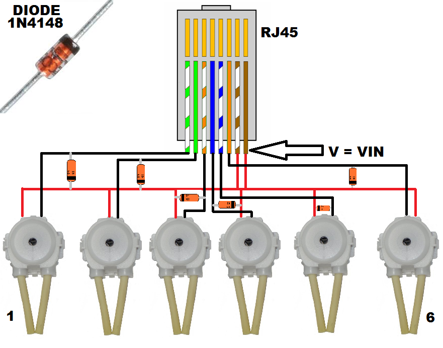
RJ45 for dosing pumps haven't a GND.
Take it from any other place.
Take it from any other place.
Post your doubts on forum because it can help another user too. Just PM me for support if it's absolutely necessary.
Post Number:#107
Thu Jan 22, 2015 10:37 pm
Posts: 274
Topics: 6 Images: 46 Solve rating: 0 Joined: Mon Sep 08, 2014 1:35 am Topics: 6
Age: 42 Location: Aurora Gender: National Flag:
Hi Fernando
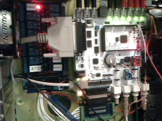
I guess the more simple question would how would I feed 12 volts to the board without over loading the voltage regulator and , my 5 volt relays? Would I just use the the DB25 VIN port or is there another way. I ask a lot because I have gotten so far and do not want to damage the board.
-------------------------------- Last edited Thu Jan 22, 2015 8:22 pm --------------------------------
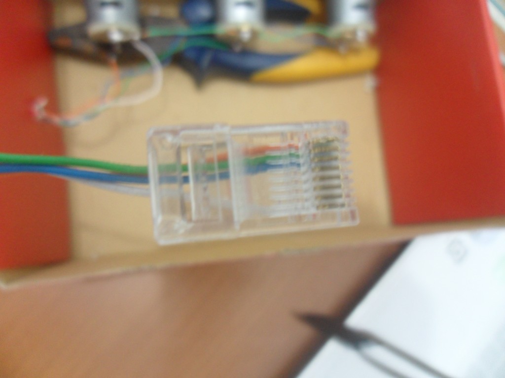
I think I have it, I used vin brown\brown&white to supply 12 volt to RJ45 then then connect to dossing pumps and it worked.
I guess the more simple question would how would I feed 12 volts to the board without over loading the voltage regulator and , my 5 volt relays? Would I just use the the DB25 VIN port or is there another way. I ask a lot because I have gotten so far and do not want to damage the board.
-------------------------------- Last edited Thu Jan 22, 2015 8:22 pm --------------------------------
I think I have it, I used vin brown\brown&white to supply 12 volt to RJ45 then then connect to dossing pumps and it worked.
Happy reefing to all.
Christopher Kindig
Christopher Kindig
Post Number:#108
Fri Jan 23, 2015 12:04 am
Posts: 274
Topics: 6 Images: 46 Solve rating: 0 Joined: Mon Sep 08, 2014 1:35 am Topics: 6
Age: 42 Location: Aurora Gender: National Flag:
ok so back to the display issue by what you have pointed out I should have 3.3 volts on the tab of the regulator, when I check it I only have 1.7 volts so I will find the schematics and Bridges the appropriate resister.
Happy reefing to all.
Christopher Kindig
Christopher Kindig
Post Number:#109
Mon Jan 26, 2015 8:26 am
Posts: 274
Topics: 6 Images: 46 Solve rating: 0 Joined: Mon Sep 08, 2014 1:35 am Topics: 6
Age: 42 Location: Aurora Gender: National Flag:
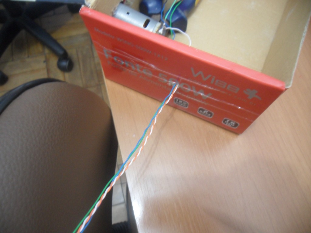
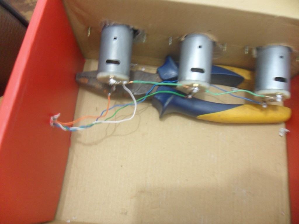
All is working now, I need to get this up to my tank after I do some clean up and finishing touches.
Happy reefing to all.
Christopher Kindig
Christopher Kindig
Post Number:#110
Tue Jan 27, 2015 8:19 am
Posts: 274
Topics: 6 Images: 46 Solve rating: 0 Joined: Mon Sep 08, 2014 1:35 am Topics: 6
Age: 42 Location: Aurora Gender: National Flag:
Hi Fernando, I connected 12 volt to brown wire from RJ45 for dosing pumps and all the strange issues I was having with my net settings went away it is working consistantly now, Iam building the box for my dossing pumps and will post some pics when it's done, my PH and ORP readings seem to very erratic any thoughts .
Happy reefing to all.
Christopher Kindig
Christopher Kindig
Post Number:#111
Tue Jan 27, 2015 11:11 am
Posts: 1699
Topics: 38 Images: 301 Solve rating: 233 Joined: Mon Mar 03, 2014 5:59 pm Topics: 38
Age: 39 Location: São Paulo Gender: National Flag:
Hi!
If the probes are on sump, maybe you have problem of electric noise.
Check page 10 of this datasheet: http://atlas-scientific.com/_files/_dat ... asheet.pdf?
So, you need of galvanic isolator: http://atlas-scientific.com/product_pag ... r-iso.html
I did a small shield to place this isolator.
I sent the project to Sueur Aurelien and he bought 10 PCB's, send a PM to him and ask if can sell a piece for you.
Best regards.
Last edited by Fernando Garcia on Wed Jan 28, 2015 10:36 am, edited 1 time in total.
Reason: Spelling.
Reason: Spelling.
Post your doubts on forum because it can help another user too. Just PM me for support if it's absolutely necessary.
Post Number:#112
Wed Jan 28, 2015 3:38 am
Posts: 274
Topics: 6 Images: 46 Solve rating: 0 Joined: Mon Sep 08, 2014 1:35 am Topics: 6
Age: 42 Location: Aurora Gender: National Flag:
I sent a pm to find out if Sueur has any to sell.
Happy reefing to all.
Christopher Kindig
Christopher Kindig
Post Number:#113
Wed Jan 28, 2015 7:46 pm
Posts: 274
Topics: 6 Images: 46 Solve rating: 0 Joined: Mon Sep 08, 2014 1:35 am Topics: 6
Age: 42 Location: Aurora Gender: National Flag:
Last edited by Fernando Garcia on Wed Jan 28, 2015 8:26 pm, edited 1 time in total.
Reason: Images fixed.
Reason: Images fixed.
Happy reefing to all.
Christopher Kindig
Christopher Kindig
Post Number:#114
Wed Jan 28, 2015 8:32 pm
Posts: 1699
Topics: 38 Images: 301 Solve rating: 233 Joined: Mon Mar 03, 2014 5:59 pm Topics: 38
Age: 39 Location: São Paulo Gender: National Flag:
Hi!
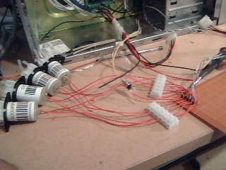
Your wiring for dosing pump can be more simple.
Put the diode directly on motor.
See how I did the wiring for my tests.
Ps. Add images bigger to your albums please. If you have difficult the convert images try a program called "Format Factory" and select the max. resolution to output as 1024 x 768. The image have good quality and small size (in bytes).
Best regards.
Post your doubts on forum because it can help another user too. Just PM me for support if it's absolutely necessary.
Post Number:#115
Wed Jan 28, 2015 9:06 pm
Posts: 274
Topics: 6 Images: 46 Solve rating: 0 Joined: Mon Sep 08, 2014 1:35 am Topics: 6
Age: 42 Location: Aurora Gender: National Flag:
Hi Fernando I look into that for the images, as for motors I want them to be easy to take out in case of problems.
Happy reefing to all.
Christopher Kindig
Christopher Kindig
Post Number:#116
Thu Jan 29, 2015 3:50 am
Posts: 70
Topics: 12 Images: 3 Solve rating: 0 Joined: Tue Oct 28, 2014 11:06 am Topics: 12
Age: 45 Gender: 
National Flag:

Christopher i found this:
Any voltage between 7 and 12 V.
If you have the board powered with 12V, this voltage will be available on connector DB25 and RJ45 on pins called V = VIN. So you can use this 12 V to supply the relay board and dosing pumps otherwise need of an external power supply.
So i am guessing you are now powering the complete board at 12v? So no more use for the 5v on the board. How is your regulator doing heat wise?
@fernando shouldn't vin actualy be vout (voltage out)?
Last edited by Ruben Wijnhoven on Thu Jan 29, 2015 3:59 am, edited 1 time in total.
Post Number:#117
Thu Jan 29, 2015 3:59 am
Posts: 274
Topics: 6 Images: 46 Solve rating: 0 Joined: Mon Sep 08, 2014 1:35 am Topics: 6
Age: 42 Location: Aurora Gender: National Flag:
Yes, I had some thing else going on. The way mine is set up now is 6 volts on vin on db25 and all is stable. I will not set 12 volts to the board it gets hotter than I like, so yes I power board and relays with 6 volts and, dosing pumps with 12 volts all from the computer power supply. I do not have the brown/brown and white wires hooked up from RJ 45.
Last edited by Christopher Kindig on Thu Jan 29, 2015 4:09 am, edited 1 time in total.
Happy reefing to all.
Christopher Kindig
Christopher Kindig
Post Number:#118
Thu Jan 29, 2015 4:01 am
Posts: 70
Topics: 12 Images: 3 Solve rating: 0 Joined: Tue Oct 28, 2014 11:06 am Topics: 12
Age: 45 Gender: National Flag:
See my post edit above. Why do you voltage in at db25? You should be able to use the normal power connector for that.
Post Number:#119
Thu Jan 29, 2015 4:11 am
Posts: 274
Topics: 6 Images: 46 Solve rating: 0 Joined: Mon Sep 08, 2014 1:35 am Topics: 6
Age: 42 Location: Aurora Gender: National Flag:
I had some issues with voltage from there. For some reason the voltage was not stable and was causing IP address to change at random as soon as I connected as I have it now alll my IP issues stopped.
Happy reefing to all.
Christopher Kindig
Christopher Kindig
Post Number:#120
Thu Jan 29, 2015 7:32 am
Posts: 1699
Topics: 38 Images: 301 Solve rating: 233 Joined: Mon Mar 03, 2014 5:59 pm Topics: 38
Age: 39 Location: São Paulo Gender: National Flag:
Hi!
It not makes sense for me. The circuit connected to V = VIN on DB25 isn't connected to any other circuit else to dosing pump.
Before power jack have a diode (next of reset button) so, the 6 volts can't go to VIN and regulator 5V.
The problem should be other and this case is only a coincidence.
What you mean?
From Ferduino specifications.
Best regards.
-------------------------------- Last edited Thu Jan 29, 2015 9:00 am --------------------------------
Add a RJ45 female to your enclosure.
Yes, I had some thing else going on. The way mine is set up now is 6 volts on vin on db25 and all is stable. I will not set 12 volts to the board it gets hotter than I like, so yes I power board and relays with 6 volts and, dosing pumps with 12 volts all from the computer power supply. I do not have the brown/brown and white wires hooked up from RJ 45.
It not makes sense for me. The circuit connected to V = VIN on DB25 isn't connected to any other circuit else to dosing pump.
Before power jack have a diode (next of reset button) so, the 6 volts can't go to VIN and regulator 5V.
The problem should be other and this case is only a coincidence.
Ruben Wijnhoven wrote:
Christopher i found this:
@fernando shouldn't vin actualy be vout (voltage out)?
@fernando shouldn't vin actualy be vout (voltage out)?
What you mean?
VIN: The input voltage to the Ferduino board when it’s using an external power source (as opposed to 5 volts from the USB connection or other regulated power source). You can supply voltage through this pin, or, if supplying voltage via the power jack, access it through this pin.
From Ferduino specifications.
Best regards.
-------------------------------- Last edited Thu Jan 29, 2015 9:00 am --------------------------------
Hi Fernando I look into that for the images, as for motors I want them to be easy to take out in case of problems.
Add a RJ45 female to your enclosure.
Post your doubts on forum because it can help another user too. Just PM me for support if it's absolutely necessary.
Return to Show your controller
Who is online
Users viewing this topic: No registered users and 2 guests