
Hi Fernando and all,
I bought an electronic return pump, the Tunze 1073.050.
Here you can find the manual with details:
https://www.tunze.com/fileadmin/gebrauc ... 3.0588.pdf
it has a power supply with an output at 24V DC 3A that goes into a controller that you can see here:
https://www.tunze.com/PT/en/products/de ... D=7090.250
I would like to use the wave maker output of Ferduino to control this pump.
I'm pretty sure that I should connect the wavemaker output to something in the controller...but I don't have the minimum idea of how.
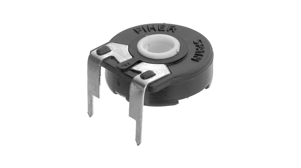
On the controller there is a potentiometer, so probably the connection should be made to its pins.
Can somebody help me in understanding how can i do this simple thing?
thank you so much, as usual.
Forum ‹ Hardware ‹ Others components ‹ Wiring for electronic pump
Wiring for electronic pump [SOLVED]
10 posts
• Page 1 of 1
Post Number:#1
 Thu Nov 02, 2017 8:45 pm
Posts: 50
Topics: 13 Solve rating: 0 Joined: Wed Sep 06, 2017 7:45 pm Topics: 13
Age: 40 Gender: 
National Flag:

Post Number:#2
Fri Nov 03, 2017 4:28 pm
Posts: 50
Topics: 13 Solve rating: 0 Joined: Wed Sep 06, 2017 7:45 pm Topics: 13
Age: 40 Gender: National Flag:
Here a picture of the controller.

Last edited by Fernando Garcia on Sat Nov 04, 2017 9:34 am, edited 1 time in total.
Reason: Please use tags [img=left][/img] to post images
Reason: Please use tags [img=left][/img] to post images
Post Number:#3
Sat Nov 04, 2017 9:32 am


Posts: 1699
Topics: 38 Images: 301 Solve rating: 233 Joined: Mon Mar 03, 2014 5:59 pm Topics: 38
Age: 39 Location: São Paulo Gender: 
National Flag:

Hi!
Measure the voltage between this two pins:
Best regards.
Measure the voltage between this two pins:
Best regards.
Post your doubts on forum because it can help another user too. Just PM me for support if it's absolutely necessary.
Post Number:#4
Sat Nov 04, 2017 3:32 pm
Posts: 50
Topics: 13 Solve rating: 0 Joined: Wed Sep 06, 2017 7:45 pm Topics: 13
Age: 40 Gender: National Flag:
2.42 V
I did what you can see in the picture. Power supply plugged into the controller. Pump not connected (but i think that it is not a problem)

thank you for helping me Fernando.
I did what you can see in the picture. Power supply plugged into the controller. Pump not connected (but i think that it is not a problem)
thank you for helping me Fernando.
Last edited by Fernando Garcia on Sun Nov 05, 2017 11:40 am, edited 1 time in total.
Reason: Please use tags [img=left][/img] to post images
Reason: Please use tags [img=left][/img] to post images
Post Number:#5
Sun Nov 05, 2017 11:43 am
Posts: 1699
Topics: 38 Images: 301 Solve rating: 233 Joined: Mon Mar 03, 2014 5:59 pm Topics: 38
Age: 39 Location: São Paulo Gender: National Flag:
Hi!
Moving the knob changes something?
Best regards.
Moving the knob changes something?
Best regards.
Post your doubts on forum because it can help another user too. Just PM me for support if it's absolutely necessary.
Post Number:#6
Sun Nov 05, 2017 2:28 pm
Posts: 50
Topics: 13 Solve rating: 0 Joined: Wed Sep 06, 2017 7:45 pm Topics: 13
Age: 40 Gender: National Flag:
No! It doesn’t change. 2.42 V stable.
Post Number:#7
Sun Nov 05, 2017 2:51 pm
Posts: 1699
Topics: 38 Images: 301 Solve rating: 233 Joined: Mon Mar 03, 2014 5:59 pm Topics: 38
Age: 39 Location: São Paulo Gender: National Flag:
You should be able to control this pump using PWM between 0 and 127 or 0 - 2.5 V.
Remove this trimmer then connect the GND pin to Ground and PWM pin to Input.
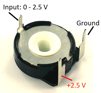
DO NOT APPLY more than 127 PWM to this input or use a voltage divider on PWM pin.
P.S.: I'm not responsible by any damage in your controller or board. Do it by your own risk.
-------------------------------- Last edited Sun Nov 05, 2017 4:02 pm --------------------------------
My suggestion for you is: buy an Arduino clone to make tests to prevent damage your Ferduino Mega.
Remove this trimmer then connect the GND pin to Ground and PWM pin to Input.
DO NOT APPLY more than 127 PWM to this input or use a voltage divider on PWM pin.
P.S.: I'm not responsible by any damage in your controller or board. Do it by your own risk.
-------------------------------- Last edited Sun Nov 05, 2017 4:02 pm --------------------------------
My suggestion for you is: buy an Arduino clone to make tests to prevent damage your Ferduino Mega.
Post your doubts on forum because it can help another user too. Just PM me for support if it's absolutely necessary.
Post Number:#8
Mon Nov 06, 2017 11:42 am
Posts: 50
Topics: 13 Solve rating: 0 Joined: Wed Sep 06, 2017 7:45 pm Topics: 13
Age: 40 Gender: National Flag:
Ok Fernando, I’ll try following your suggestions and I let you know.
Thank you
Thank you
Post Number:#9
Sat Nov 11, 2017 6:09 pm
Posts: 50
Topics: 13 Solve rating: 0 Joined: Wed Sep 06, 2017 7:45 pm Topics: 13
Age: 40 Gender: National Flag:
Hi Fernando and guys,
I tried your suggestions with another Arduino that I have. It works but with a little modification.
I think that it is because the pump with the trimmer can not be regulated between 0 and 100% of power...but between 20% and 100%. So removing totally the trimmer the pump controller doesn't work. Otherwise removing just the INPUT pin of the trimmer and connecting arduino's GND and input where indicated by Fernando it works very well (exactly as using the trimmer).
Obviously I confirm that should be used a range 0-127 for the Arduino's Output.
In some weeks I'll perform a final trial with Ferduino Mega and the pump connected.
thank you all!
Post Number:#10
Sun Nov 12, 2017 11:58 am
Posts: 1699
Topics: 38 Images: 301 Solve rating: 233 Joined: Mon Mar 03, 2014 5:59 pm Topics: 38
Age: 39 Location: São Paulo Gender: National Flag:
Hi!
What you are talking doesn't makes sense to me since leaving the trimmer connected between 2.5 V and GND it will work like a simple resistor spending energy only.
Maybe the controller doesn't supports PWM control so the alternative is add a ceramic capacitor of 1 uF between PWM pin and GND.
Best regards.
Post your doubts on forum because it can help another user too. Just PM me for support if it's absolutely necessary.
10 posts
• Page 1 of 1
Who is online
Users viewing this topic: No registered users and 1 guest