
Hello Fernando,
I am using PCF8575(sparkfun breakout board) with ULN2803.
My config is as follow:
PCF8575
SDA > pin 20 (I did not use resistor because I have supposed that they are on the breakout board (R1,R2,R3))
SCL >pin 21 (same remark)
Gnd > Gnd Arduino
VCC >+5 Arduino
A0,A1,A2 > Gnd (weld between central pad and right pad (at the back of the breakout board )
P00-P05 > PIN 1-5 ULN2803
ULN2803
Pin 1-5 > P00-P05 PCF8575
Pin 9 > Gnd Arduino
Voltage check on output pin PCF8575(P00-P05) gives 4.82 (timer ON) or 0V (timer OFF).
Regarding those values,I can suppose that my PCF8575 is working properly.
My problem is that once I connect P00-P05 to pin 1-5 of the ULN2803,voltage drops to 1.7 V on input pin ULN2803 and to 0.44V on output pin (voltage drop between input and output is correct I think) but why does the voltage drops to 1.7V on input pin with the consequence that it's not possible to trigger a relay with 0.44V on output.
Could you please help me
Once again thank you very much for your help and for the superb project that you offer to us
Best regards
Jean-Yves
Forum ‹ Members section ‹ DIY Ferduino controller ‹ PCF8575 and ULN2803
PCF8575 and ULN2803 [SOLVED]
6 posts
• Page 1 of 1
Post Number:#1
 Wed Nov 26, 2014 12:22 pm
Posts: 30
Topics: 7 Images: 32 Solve rating: 0 Joined: Fri May 09, 2014 2:30 pm Topics: 7
Age: 64 Location: waremme Gender: 
National Flag:

Post Number:#2
Wed Nov 26, 2014 1:27 pm


Posts: 1699
Topics: 38 Images: 301 Solve rating: 233 Joined: Mon Mar 03, 2014 5:59 pm Topics: 38
Age: 39 Location: São Paulo Gender: National Flag:

Hi!
If your module is like this:

Exists only the pads to resistors. Need add resistors of 10 K.
When the ULN is connected is normal have 1.5 - 1.7 V.
What's the model of your relay board?
It have inverted logic, I mean turn on with LOW and turn off with HIGH signal?
Best regards.
If your module is like this:
Exists only the pads to resistors. Need add resistors of 10 K.
When the ULN is connected is normal have 1.5 - 1.7 V.
What's the model of your relay board?
It have inverted logic, I mean turn on with LOW and turn off with HIGH signal?
Best regards.
Post your doubts on forum because it can help another user too. Just PM me for support if it's absolutely necessary.
Post Number:#3
Wed Nov 26, 2014 2:37 pm
Posts: 30
Topics: 7 Images: 32 Solve rating: 0 Joined: Fri May 09, 2014 2:30 pm Topics: 7
Age: 64 Location: waremme Gender: National Flag:
Hello again Fernando,
This is well the board that I use.
Following your answer, I have added 2 10K resistors.
This is the link to my relay board.
http://www.ebay.com/itm/8-Channel-5V-Re ... 1317483666.
May be my problem comes from the way to connect this relay board.
Thanks again
Jean-Yves
This is well the board that I use.
Following your answer, I have added 2 10K resistors.
This is the link to my relay board.
http://www.ebay.com/itm/8-Channel-5V-Re ... 1317483666.
May be my problem comes from the way to connect this relay board.
Thanks again
Jean-Yves
Post Number:#4
Wed Nov 26, 2014 3:09 pm
Posts: 1699
Topics: 38 Images: 301 Solve rating: 233 Joined: Mon Mar 03, 2014 5:59 pm Topics: 38
Age: 39 Location: São Paulo Gender: National Flag:
You can test it connecting IN1 - IN8 directly to GND.
Check if the jumper is in right position (JD-VCC / VCC) .
Here's the basic circuit for this board.
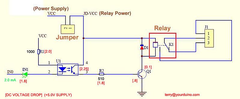
Moreover for this quantity of relays I think better use an external power supply connected between JD-VCC and GND.
Check if the jumper is in right position (JD-VCC / VCC) .
Here's the basic circuit for this board.
Moreover for this quantity of relays I think better use an external power supply connected between JD-VCC and GND.
Post your doubts on forum because it can help another user too. Just PM me for support if it's absolutely necessary.
Post Number:#5
Wed Nov 26, 2014 3:31 pm
Posts: 30
Topics: 7 Images: 32 Solve rating: 0 Joined: Fri May 09, 2014 2:30 pm Topics: 7
Age: 64 Location: waremme Gender: National Flag:
Thank you Fernando,
Just finished rewiring my breadboard using opto-isolation for Arduino and an external power source connected to Gnd and JD-VCC.
Everything works fine.
I can now continue the design of my PCB ( I test each part of ferduino separetly on a breadboard and if it's OK I convert it to my PCB project).
Thanks again
Jean-Yves
Post Number:#6
Wed Nov 26, 2014 3:39 pm
Posts: 1699
Topics: 38 Images: 301 Solve rating: 233 Joined: Mon Mar 03, 2014 5:59 pm Topics: 38
Age: 39 Location: São Paulo Gender: National Flag:
Glad to hear!
Post your doubts on forum because it can help another user too. Just PM me for support if it's absolutely necessary.
6 posts
• Page 1 of 1
Return to DIY Ferduino controller
Who is online
Users viewing this topic: No registered users and 1 guest