Forum Members section DIY Ferduino controller Add WiFi with less than $5

Add WiFi with less than $5

Ask here about your controller made with pieces purchased in other shops.

Post Number:#1 Post Fri Dec 16, 2016 7:59 am
Posts: 1699
Topics: 38
Images: 301
Solve rating: 233
Joined: Mon Mar 03, 2014 5:59 pm
Topics: 38
Age: 40
Location: São Paulo
Gender: Male
National Flag:
Brazil

Hi!

I'm happy to say now is possible add WIFI to your DIY controller with less than $5.

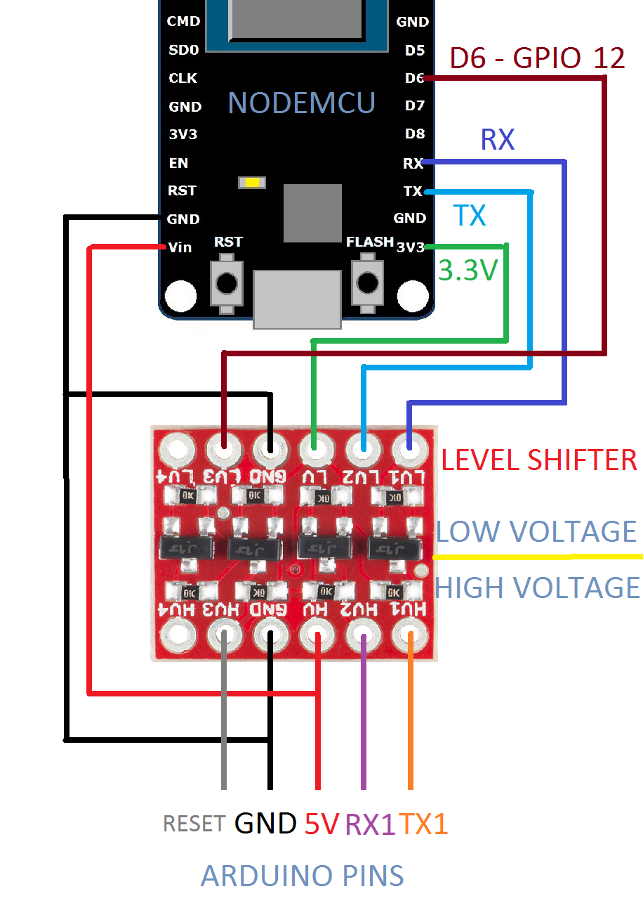
For it is needed a NodeMCU and a logic level shifter because it works with 3.3V.

I'm using a NodeMCU V3 because it has an ESP-12 and USB interface built-in and it's very cheap.

Parts:

1 x NodeMCU V3 ;
1 x Logic level shifter 5 to 3.3 V

Wiring:

Image


See the video to learn how to set up the MQTT client.

Warning: Don't forget to turn off the UART debug log in ESP-link interface.

Watch on youtube.com


Enjoy! :)

PS. Any model of ESP8266 supported by ESP-link can be used but please do not ask me how to make the wiring to change the firmware.
Post your doubts on forum because it can help another user too. Just PM me for support if it's absolutely necessary.

Post Number:#2 Post Wed Jun 09, 2021 4:32 pm
Posts: 1699
Topics: 38
Images: 301
Solve rating: 233
Joined: Mon Mar 03, 2014 5:59 pm
Topics: 38
Age: 40
Location: São Paulo
Gender: Male
National Flag:
Brazil

Hi!

I found a better way to add WiFi to Ferduino. This is not a $5 solution but at least no soldering is required and the build will be more clean.

Image


This board by RobotDyn has built-in an ESP8266.

You can follow the video above, you have just to set the dip switches in right position to each situation.

To upload the firmware (ESP-link) to ESP8266:

Switches 1, 2, 3 and 4 = OFF
Switches 5, 6 and 7 = ON
Switch 8 is not used!

To see the debug messages from ESP8266 serial port:

Switches 1, 2, 3, 4 and 7= OFF
Switches 5 and 6 = ON
Switch 8 is not used!

To upload upload sketch (Ferduino or test codes) to ATmega2560:

Switches 1, 2, 5, 6 and 7= OFF
Switches 3 and 4 = ON
Switch 8 is not used!

To see debug messages from ATmega2560 serial port:

Switches 1, 2, 5, 6 and 7= OFF
Switches 3 and 4 = ON
Switch 8 is not used!

To enable communication between ATmega2560 and ESP8266 after install Ferduino (or test code) and ESP-link.

Switches 3, 4, 5, 6 and 7= OFF
Switches 1 and 2 = ON
Switch 8 is not used!

The Ferduino (and test code) is using the Serial 3 to communication between ESP8266 and ATmega2560 so you should place the smaller switch to position TXD3/RXD3.

Since Serial3 now is used for ESP8266 so Serial1 should be used for stamps.

To use this RobotDyn board you should download the branch RobotDyn_Mega_WiFi available here.

Enjoy!

P.S. I haven't RobotDyn board so if there's some error in my instructions let me know.
Post your doubts on forum because it can help another user too. Just PM me for support if it's absolutely necessary.


Return to DIY Ferduino controller


Who is online

Users viewing this topic: No registered users and 1 guest

cron