
Good morning and sorry for this silly question. I tried to find a wire to be able to separate the TFT shield from the screen but I only find IDE 40 pin cables and you have to modify one of the ends as it is not directly useful.
Are there wires already made? Or should I manually modify a standard IDE wire
Thank you very much
PS: searching the forum I have not found an answer either. And apologies for my bad English
Forum ‹ Members section ‹ DIY Ferduino controller ‹ Extension wire TFT shield to screen
Extension wire TFT shield to screen [SOLVED]
7 posts
• Page 1 of 1
Post Number:#1
 Sat Jul 08, 2017 7:07 am
Posts: 65
Topics: 18 Images: 32 Solve rating: 0 Joined: Fri Jun 16, 2017 6:23 am Topics: 18
Age: 61 Gender: 
National Flag:

Post Number:#2
Sat Jul 08, 2017 9:36 am


Posts: 1699
Topics: 38 Images: 301 Solve rating: 233 Joined: Mon Mar 03, 2014 5:59 pm Topics: 38
Age: 39 Location: São Paulo Gender: 
National Flag:

Hi!
You are using wrong words
Try this:
search.php?keywords=flat+cable&terms=all&author=&sv=0&sc=1&sf=all&sr=posts&sk=t&sd=d&st=0&ch=300&t=0&submit=Search
On Ebay search for "40 Pin Male to Female IDE Flat Ribbon Cable".
Here a result: http://www.ebay.com/itm/172768223884
Best regards.
You are using wrong words
Try this:
search.php?keywords=flat+cable&terms=all&author=&sv=0&sc=1&sf=all&sr=posts&sk=t&sd=d&st=0&ch=300&t=0&submit=Search
On Ebay search for "40 Pin Male to Female IDE Flat Ribbon Cable".
Here a result: http://www.ebay.com/itm/172768223884
Best regards.
Post your doubts on forum because it can help another user too. Just PM me for support if it's absolutely necessary.
Post Number:#3
Sat Jul 08, 2017 1:20 pm
Posts: 65
Topics: 18 Images: 32 Solve rating: 0 Joined: Fri Jun 16, 2017 6:23 am Topics: 18
Age: 61 Gender: National Flag:
I'm sorry to explain so badly, if I found IDE cable but what happens is what I try to show in the following scheme.

I hope you understand the drawing. Thank you
I hope you understand the drawing. Thank you
Post Number:#4
Sat Jul 08, 2017 1:45 pm
Posts: 1699
Topics: 38 Images: 301 Solve rating: 233 Joined: Mon Mar 03, 2014 5:59 pm Topics: 38
Age: 39 Location: São Paulo Gender: National Flag:
Crossing the wires TFT won't work.
It should match 1 to 1, 2 to 2 and so on.
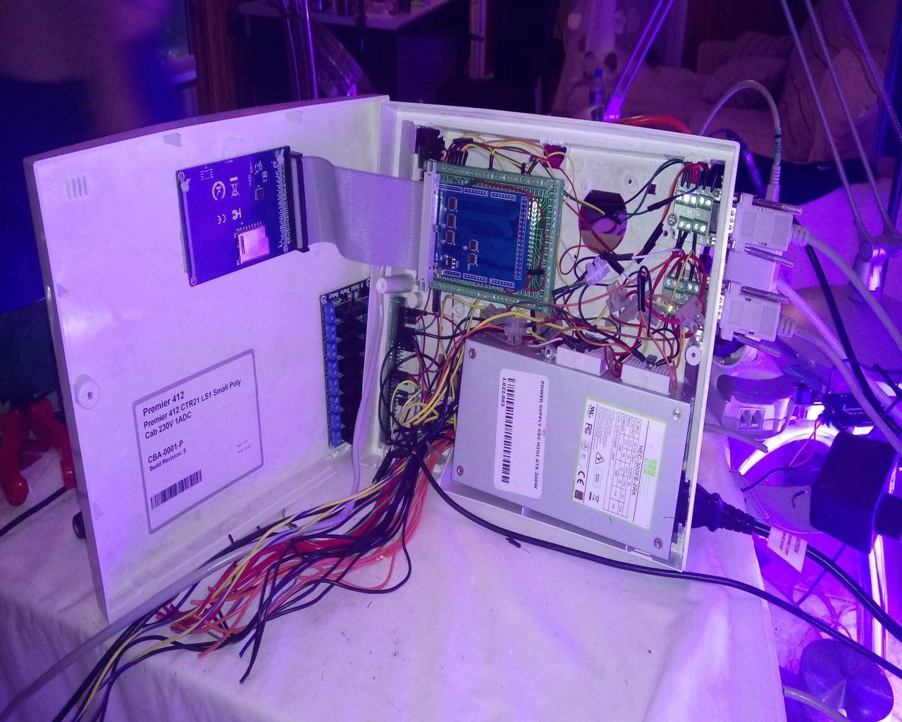
Here an example with flat cable connected:
It should match 1 to 1, 2 to 2 and so on.
Here an example with flat cable connected:
Post your doubts on forum because it can help another user too. Just PM me for support if it's absolutely necessary.
Post Number:#5
Sat Jul 08, 2017 10:03 pm
Posts: 65
Topics: 18 Images: 32 Solve rating: 0 Joined: Fri Jun 16, 2017 6:23 am Topics: 18
Age: 61 Gender: National Flag:
In my case what happens with the two IDE cables I've tried is the following:
For example, pin 40 is marked with the red arrows and for it to work I think the continuity should be with the green arrow.

Regards,
For example, pin 40 is marked with the red arrows and for it to work I think the continuity should be with the green arrow.
Regards,
Post Number:#6
Sun Jul 09, 2017 4:23 am
Posts: 65
Topics: 18 Images: 32 Solve rating: 0 Joined: Fri Jun 16, 2017 6:23 am Topics: 18
Age: 61 Gender: National Flag:
I think the solution would be to use a cable like the link (Post Number: #5) but shorter.
http://ferduino.com/forum/viewtopic.php?f=24&t=354&p=2774&hilit=flat+cable#p2774
I wanted to know if they exist commercially or should I manufacture it myself. Thank you
http://ferduino.com/forum/viewtopic.php?f=24&t=354&p=2774&hilit=flat+cable#p2774
I wanted to know if they exist commercially or should I manufacture it myself. Thank you
Post Number:#7
Sun Jul 09, 2017 8:14 am
Posts: 1699
Topics: 38 Images: 301 Solve rating: 233 Joined: Mon Mar 03, 2014 5:59 pm Topics: 38
Age: 39 Location: São Paulo Gender: National Flag:
Hi!
Your cable seems female to female but should be female to male.
Best regards.
Your cable seems female to female but should be female to male.
Best regards.
Post your doubts on forum because it can help another user too. Just PM me for support if it's absolutely necessary.
7 posts
• Page 1 of 1
Return to DIY Ferduino controller
Who is online
Users viewing this topic: No registered users and 1 guest