
I come back from my novice doubts
1 / If PCF8575 is used the pins 47 (ozonizer), 48 (CO2 reactor), A6, A7 and A8 would be free?
2 / In case of using ESP8266 as wifi module could the pins 16 and 17 of the multiplexer of stamps be moved to the pins 47 and 48? Or would it be possible to use the analog pins A6 and A7?
3 / using PCF8575 to the relay module 1 would only the heater pin 42 and the cooler pin 43?
Thanks
Forum ‹ Members section ‹ DIY Ferduino controller ‹ Doubts using ESP8266 and PCF8575
Doubts using ESP8266 and PCF8575 [SOLVED]
6 posts
• Page 1 of 1
Post Number:#1
 Mon Aug 28, 2017 2:57 pm
Posts: 65
Topics: 18 Images: 32 Solve rating: 0 Joined: Fri Jun 16, 2017 6:23 am Topics: 18
Age: 61 Gender: 
National Flag:

Post Number:#2
Mon Aug 28, 2017 7:46 pm


Posts: 1699
Topics: 38 Images: 301 Solve rating: 233 Joined: Mon Mar 03, 2014 5:59 pm Topics: 38
Age: 39 Location: São Paulo Gender: 
National Flag:

Post Number:#3
Tue Aug 29, 2017 4:01 am
Posts: 65
Topics: 18 Images: 32 Solve rating: 0 Joined: Fri Jun 16, 2017 6:23 am Topics: 18
Age: 61 Gender: National Flag:
Sorry for my low level of English,
I mean if I use the PCF8575 then the relay-1 module (RJ45) would only connect the pins 42 and 43 since the rest A6, A7, A8, 47 and 48 would go to the relay-2 module (DB25).
And I understand that the pins 16 and 17 of the multiplexer of stamps can be moved indistinctly to digital or analogical pins. Is it so?
Thanks again
Post Number:#4
Tue Aug 29, 2017 7:46 pm
Posts: 1699
Topics: 38 Images: 301 Solve rating: 233 Joined: Mon Mar 03, 2014 5:59 pm Topics: 38
Age: 39 Location: São Paulo Gender: National Flag:
Hi!
You are wrong this pins remains free.
If you are following Ferduino Mega schematic you will see only pins from PCF on DB25.
And I understand that the pins 16 and 17 of the multiplexer of stamps can be moved indistinctly to digital or analogical pins. Is it so?
Of course!
Best regards.
I mean if I use the PCF8575 then the relay-1 module (RJ45) would only connect the pins 42 and 43 since the rest A6, A7, A8, 47 and 48 would go to the relay-2 module (DB25).
You are wrong this pins remains free.
If you are following Ferduino Mega schematic you will see only pins from PCF on DB25.
And I understand that the pins 16 and 17 of the multiplexer of stamps can be moved indistinctly to digital or analogical pins. Is it so?
Of course!
Best regards.
Post your doubts on forum because it can help another user too. Just PM me for support if it's absolutely necessary.
Post Number:#5
Wed Aug 30, 2017 5:12 am
Posts: 65
Topics: 18 Images: 32 Solve rating: 0 Joined: Fri Jun 16, 2017 6:23 am Topics: 18
Age: 61 Gender: National Flag:
Fernando apologizes for my lack of knowledge and my English.
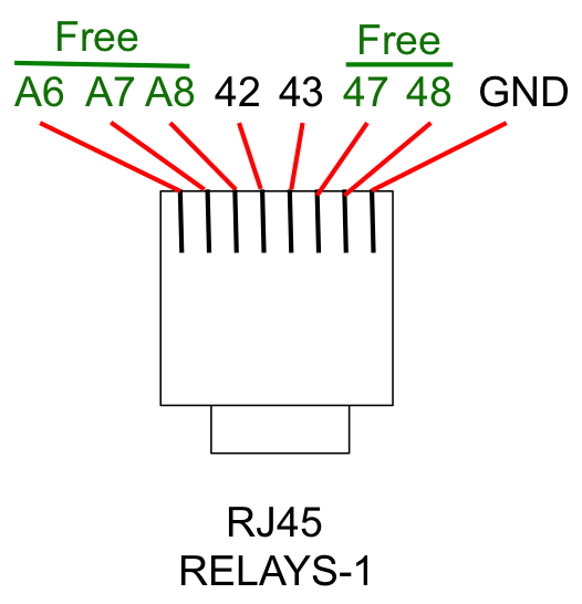
If I did not misunderstand in case of using PCF the RJ45 corresponding to the module of relays 1 would be as follows and only the pins 42 and 43 would be connected and the rest would be free.
It is right?
Thanks
If I did not misunderstand in case of using PCF the RJ45 corresponding to the module of relays 1 would be as follows and only the pins 42 and 43 would be connected and the rest would be free.
It is right?
Thanks
Post Number:#6
Wed Aug 30, 2017 9:25 am
Posts: 1699
Topics: 38 Images: 301 Solve rating: 233 Joined: Mon Mar 03, 2014 5:59 pm Topics: 38
Age: 39 Location: São Paulo Gender: National Flag:
Hi!
It's exactly as Ferduino Mega.
You can connect the pin to any connector doesn't matter if it will be used now or later.
Best regards.
It's exactly as Ferduino Mega.
You can connect the pin to any connector doesn't matter if it will be used now or later.
Best regards.
Post your doubts on forum because it can help another user too. Just PM me for support if it's absolutely necessary.
6 posts
• Page 1 of 1
Return to DIY Ferduino controller
Who is online
Users viewing this topic: No registered users and 1 guest