
A curious thing happens to me that does not make sense to me. I have connected Arduino through an ATX power supply to 12 v and under voltage with a steepdown. Well, if I use an extension cable from the shield to the screen only works up to 6 v and if I use more voltage the information on the screen is displayed but the touch does not work.
It is normal?
Thank you
Forum ‹ Members section ‹ DIY Ferduino controller ‹ Doubt with power and extension cable screen
Doubt with power and extension cable screen [SOLVED]
4 posts
• Page 1 of 1
Post Number:#1
 Tue Nov 28, 2017 2:25 pm
Posts: 65
Topics: 18 Images: 32 Solve rating: 0 Joined: Fri Jun 16, 2017 6:23 am Topics: 18
Age: 61 Gender: 
National Flag:

Post Number:#2
Tue Nov 28, 2017 8:32 pm


Posts: 1699
Topics: 38 Images: 301 Solve rating: 233 Joined: Mon Mar 03, 2014 5:59 pm Topics: 38
Age: 39 Location: São Paulo Gender: 
National Flag:

Hi!
The minimum voltage should be 7V.
If you have problem when the voltage is more than 7V it should be overheating.
Try add a fan to cool down the Arduino's voltage regulator.
Best regards.
The minimum voltage should be 7V.
If you have problem when the voltage is more than 7V it should be overheating.
Try add a fan to cool down the Arduino's voltage regulator.
Best regards.
Post your doubts on forum because it can help another user too. Just PM me for support if it's absolutely necessary.
Post Number:#3
Wed Nov 29, 2017 6:20 am
Posts: 65
Topics: 18 Images: 32 Solve rating: 0 Joined: Fri Jun 16, 2017 6:23 am Topics: 18
Age: 61 Gender: National Flag:
What I do not understand is the reason why if the screen is attached to the shield works perfectly at 8v, is when I use the extension cable between the shield and the screen when I must limit the voltage to 6v (if I use more the screen looks but touch does not work).
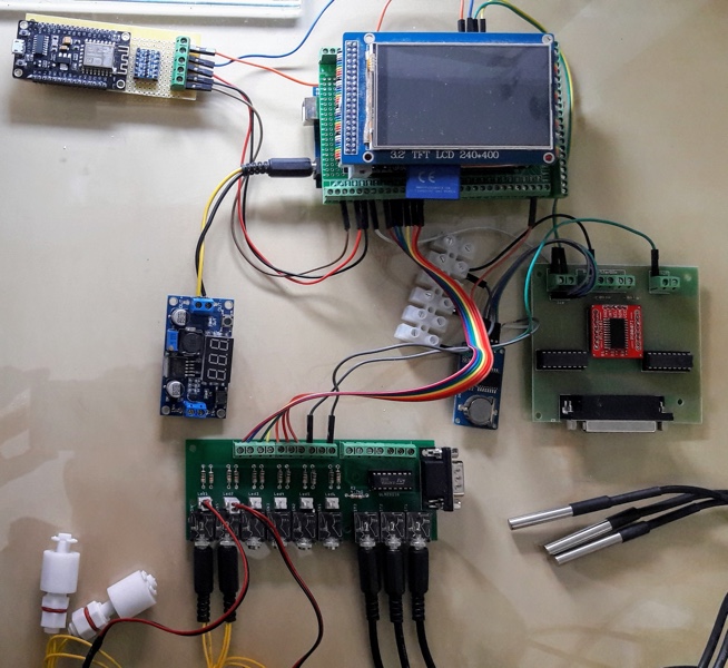
I have the whole system powered from the ATX power supply.
This is the provisional assembly that I have:
1 / PCB with all the water level, temperature and dosing pumps.
2 / PCB for relay module with PCN8575 and clock.
3 / WiFi Module
In the photo the WiFi module was powered from Arduino but currently from the ATX power supply.
I go very slowly, but I started from 0 and I prefer to settle knowledge and understand what I do.
Thank you very much
Post Number:#4
Wed Nov 29, 2017 8:58 am
Posts: 1699
Topics: 38 Images: 301 Solve rating: 233 Joined: Mon Mar 03, 2014 5:59 pm Topics: 38
Age: 39 Location: São Paulo Gender: National Flag:
Hi!
Using long wires the voltage will drop so the TFT won't work correctly.
Using high voltage the regulator will overheat then drop the voltage.
Measure the voltage on 5V circuit and in your IDE cable.
P.S. If you are using a good ATX this step down is not needed. Connect the 5V from power supply directly to 5v pin.
Best regards.
Post your doubts on forum because it can help another user too. Just PM me for support if it's absolutely necessary.
4 posts
• Page 1 of 1
Return to DIY Ferduino controller
Who is online
Users viewing this topic: No registered users and 1 guest