

Hi!
Show me the schematic of your PCB.
Also make sure that the GND from Relay board is connected to Arduino GND.
Best regards.
Forum ‹ Members section ‹ DIY Ferduino controller ‹ Pcf8575 problem
Pcf8575 problem [SOLVED]
70 posts
• Page 2 of 4 • 1, 2, 3, 4
Post Number:#21
 Wed Feb 27, 2019 8:13 pm
Posts: 1699
Topics: 38 Images: 301 Solve rating: 233 Joined: Mon Mar 03, 2014 5:59 pm Topics: 38
Age: 39 Location: São Paulo Gender: 
National Flag:

Post your doubts on forum because it can help another user too. Just PM me for support if it's absolutely necessary.
Post Number:#22
Thu Feb 28, 2019 5:55 am

Posts: 24
Topics: 7 Images: 5 Solve rating: 0 Joined: Wed Dec 05, 2018 5:23 pm Topics: 7
Age: 42 Gender: 
National Flag:

Hi Fernando,
I forward you the schematic of the board.
The strange thing is that with a pcf8575 module everything work and with the other not.
at the moment I'm feeding the relays with the arduino's 5v and gnd.
the difference I notice between the two modules that the working one has an integrated resistor
thanks a lot
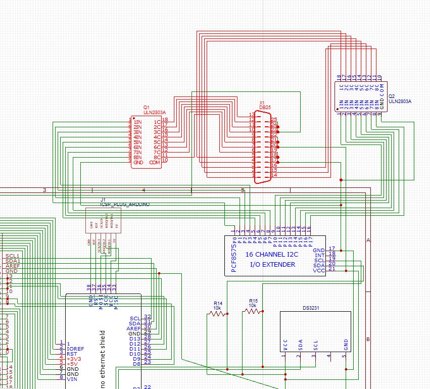
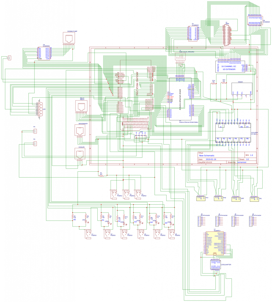
Post Number:#23
Thu Feb 28, 2019 10:19 am
Posts: 1699
Topics: 38 Images: 301 Solve rating: 233 Joined: Mon Mar 03, 2014 5:59 pm Topics: 38
Age: 39 Location: São Paulo Gender: National Flag:
Hi!
You can't feed relays using Arduino 5V, there's no enough current for it.
You should use an external power supply.
Best regards.
You can't feed relays using Arduino 5V, there's no enough current for it.
You should use an external power supply.
Best regards.
Post your doubts on forum because it can help another user too. Just PM me for support if it's absolutely necessary.
Post Number:#24
Sat Mar 02, 2019 10:46 am
Posts: 24
Topics: 7 Images: 5 Solve rating: 0 Joined: Wed Dec 05, 2018 5:23 pm Topics: 7
Age: 42 Gender: National Flag:
Hi Fernando,
Unfortunately even feeding the relay separately (gnd common) the pcf8575 sparkfun style does not work while the other is fine.
I ordered another to try if what I have is faulty but I don't think so
Do you think the schematic is correct?
Thank you again!
Unfortunately even feeding the relay separately (gnd common) the pcf8575 sparkfun style does not work while the other is fine.
I ordered another to try if what I have is faulty but I don't think so
Do you think the schematic is correct?
Thank you again!
Post Number:#25
Sat Mar 02, 2019 1:04 pm
Posts: 1699
Topics: 38 Images: 301 Solve rating: 233 Joined: Mon Mar 03, 2014 5:59 pm Topics: 38
Age: 39 Location: São Paulo Gender: National Flag:
Hi!
Schematic seems correct to me.
Best regards.
Schematic seems correct to me.
Best regards.
Post your doubts on forum because it can help another user too. Just PM me for support if it's absolutely necessary.
Post Number:#26
Fri Apr 05, 2019 3:32 pm

Posts: 1
Solve rating: 0 Joined: Thu Apr 04, 2019 2:51 pm Age: 36 Gender: National Flag:

Hi...i haven't looked at this ic before but scanning the datasheet in a minute it looks like this chip does NOT have any registers or commands for reading back the written data. You can only use it to write data to the ports or read data from the ports (if you made them logic 1 on forehand). So no you can not read back data you earlier sent.
Post Number:#27
Sun Apr 07, 2019 11:44 am
Posts: 1699
Topics: 38 Images: 301 Solve rating: 233 Joined: Mon Mar 03, 2014 5:59 pm Topics: 38
Age: 39 Location: São Paulo Gender: National Flag:
Hi!
Welcome Roch!
Gio, the problem was solved?
Have you tested with new module?
Best regards.
Welcome Roch!
Gio, the problem was solved?
Have you tested with new module?
Best regards.
Post your doubts on forum because it can help another user too. Just PM me for support if it's absolutely necessary.
Post Number:#28
Tue Apr 09, 2019 9:57 am
Posts: 24
Topics: 7 Images: 5 Solve rating: 0 Joined: Wed Dec 05, 2018 5:23 pm Topics: 7
Age: 42 Gender: National Flag:
hi Fernardo!!
unfortunately not.
I also tried the new pcf8575 but it gives the same problem.
the relay lights on dimly and doesn't work.
with the other pcf8575 everything works perfectly (https://www.ebay.com/itm/PCF8575-16-bit ... Swqlha-Pgs).
I really can't understand what the problem is...
unfortunately not.
I also tried the new pcf8575 but it gives the same problem.
the relay lights on dimly and doesn't work.
with the other pcf8575 everything works perfectly (https://www.ebay.com/itm/PCF8575-16-bit ... Swqlha-Pgs).
I really can't understand what the problem is...
Post Number:#29
Tue Apr 09, 2019 10:01 am
Posts: 1699
Topics: 38 Images: 301 Solve rating: 233 Joined: Mon Mar 03, 2014 5:59 pm Topics: 38
Age: 39 Location: São Paulo Gender: National Flag:
Hi!
Can you show me some pics?
Best regards.
Can you show me some pics?
Best regards.
Post your doubts on forum because it can help another user too. Just PM me for support if it's absolutely necessary.
Post Number:#30
Thu Apr 11, 2019 2:56 pm
Posts: 65
Topics: 18 Images: 32 Solve rating: 0 Joined: Fri Jun 16, 2017 6:23 am Topics: 18
Age: 61 Gender: National Flag:

Apologies for intruding on the thread, but the same thing happens to me.
With this type of module (PCF8575) the leds of relays are weakly illuminated but are not able to activate the relays.
I have now requested the model that indicates Gio (PCF8575 2) to test if this works, the bad thing is that the design of my PCB is for the model that in principle does not work.
As soon as I arrive and can try confirm the module.
Regards,
Post Number:#31
Sat Apr 13, 2019 1:43 pm
Posts: 1699
Topics: 38 Images: 301 Solve rating: 233 Joined: Mon Mar 03, 2014 5:59 pm Topics: 38
Age: 39 Location: São Paulo Gender: National Flag:
Hi!
If do you have problem yet can you answer my last question?
I thought the problem was solved.
Best regards.
If do you have problem yet can you answer my last question?
I thought the problem was solved.
Best regards.
Post your doubts on forum because it can help another user too. Just PM me for support if it's absolutely necessary.
Post Number:#32
Sun Apr 14, 2019 7:37 am
Posts: 65
Topics: 18 Images: 32 Solve rating: 0 Joined: Fri Jun 16, 2017 6:23 am Topics: 18
Age: 61 Gender: National Flag:
Sorry, I was still doing tests, the voltage was about 0.37 v and continued with the same problems. I used another 5v relay module and another PCB with a different PCF8575 and still had the same problems. I had left it as impossible and decided not to use the PCF module even if I limited some of the functionalities.
As soon as the new module that Gio indicated that it worked for me, I will try and comment on it.
Regards,
As soon as the new module that Gio indicated that it worked for me, I will try and comment on it.
Regards,
Post Number:#33
Sun Apr 14, 2019 10:47 am
Posts: 1699
Topics: 38 Images: 301 Solve rating: 233 Joined: Mon Mar 03, 2014 5:59 pm Topics: 38
Age: 39 Location: São Paulo Gender: National Flag:
The voltage should be around 1.5 V with ULN connected.
Disconnect the ULN and measure the voltage. It should be 5V.
Maybe the input voltage on PCF is less than 5V.
Disconnect the ULN and measure the voltage. It should be 5V.
Maybe the input voltage on PCF is less than 5V.
Post your doubts on forum because it can help another user too. Just PM me for support if it's absolutely necessary.
Post Number:#34
Mon Dec 16, 2019 2:34 pm
Posts: 1699
Topics: 38 Images: 301 Solve rating: 233 Joined: Mon Mar 03, 2014 5:59 pm Topics: 38
Age: 39 Location: São Paulo Gender: National Flag:
Hi!
Any news here?
Best regards.
Any news here?
Best regards.
Post your doubts on forum because it can help another user too. Just PM me for support if it's absolutely necessary.
Post Number:#35
Mon Dec 16, 2019 2:35 pm
Posts: 1699
Topics: 38 Images: 301 Solve rating: 233 Joined: Mon Mar 03, 2014 5:59 pm Topics: 38
Age: 39 Location: São Paulo Gender: National Flag:
Hi!
Any news here?
Best regards.
Any news here?
Best regards.
Post your doubts on forum because it can help another user too. Just PM me for support if it's absolutely necessary.
Post Number:#36
Tue Dec 17, 2019 7:43 pm
Posts: 24
Topics: 7 Images: 5 Solve rating: 0 Joined: Wed Dec 05, 2018 5:23 pm Topics: 7
Age: 42 Gender: National Flag:
Hi Fernando,
Unfortunately not.
I've tried several PCF8575 cards but none goes.
With this model (https://m.geekbuying.com/item/OPRN-SMAR ... 82026.html) everything works fine even though I am very uncomfortable because I designed the card for the other PCF8575 model. The wiring is exactly the one indicated by you but without connecting the vdd and the gnd to the side of the board.
Best regards
Post Number:#37
Wed Dec 18, 2019 11:06 am
Posts: 1699
Topics: 38 Images: 301 Solve rating: 233 Joined: Mon Mar 03, 2014 5:59 pm Topics: 38
Age: 39 Location: São Paulo Gender: National Flag:
Hi!
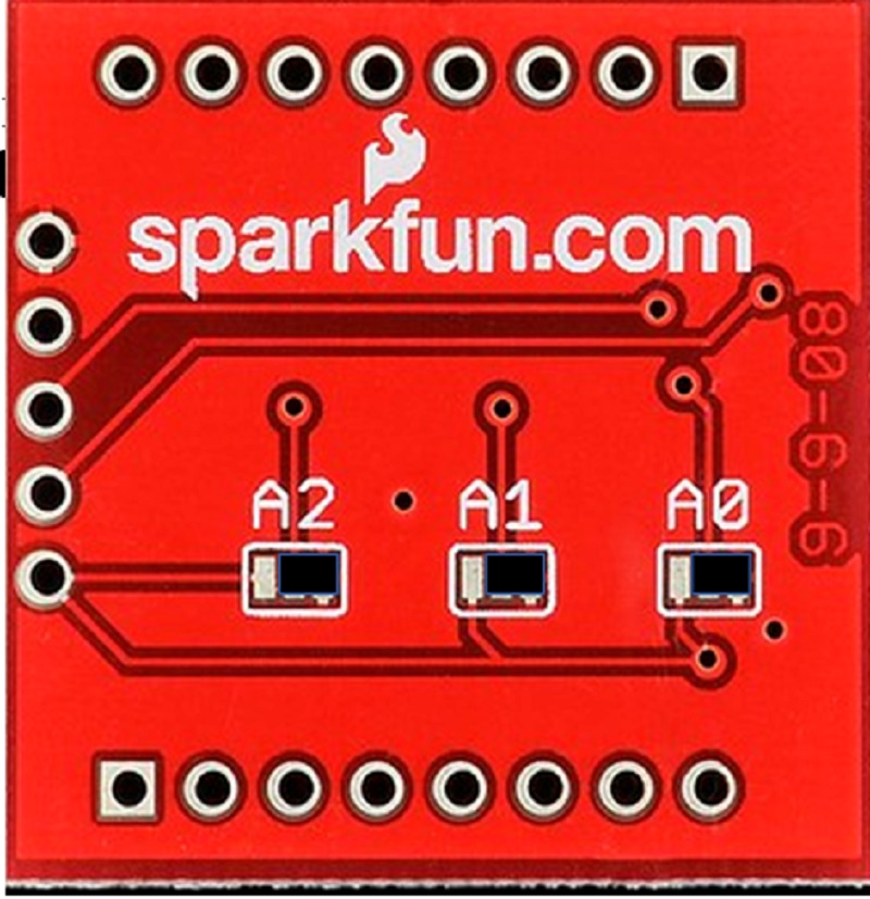
Did you a shunts on bottom side to A0, A1 and A2?

It should be center to right (GND)
Did you a test with this module in a breadboard?
Best regards.
Did you a shunts on bottom side to A0, A1 and A2?
It should be center to right (GND)
Did you a test with this module in a breadboard?
Best regards.
Post your doubts on forum because it can help another user too. Just PM me for support if it's absolutely necessary.
Post Number:#38
Sat Dec 21, 2019 11:26 am
Posts: 65
Topics: 18 Images: 32 Solve rating: 0 Joined: Fri Jun 16, 2017 6:23 am Topics: 18
Age: 61 Gender: National Flag:
Apologies for entering the thread, as I said to me the same thing happens to Gio. Fernando seeing your answer I think the problem is due to the fact that A0, A1 and A2 are not welded with GND (the Sparkfun shield is the same as the photo you show). I understand that it is necessary to bridge by welding from the central point to the one on the left and free the one on the left at A0, A1 and A2. It is right?
Thank you
Thank you
Post Number:#39
Sat Dec 21, 2019 12:22 pm
Posts: 1699
Topics: 38 Images: 301 Solve rating: 233 Joined: Mon Mar 03, 2014 5:59 pm Topics: 38
Age: 39 Location: São Paulo Gender: National Flag:
Hi!
José, there's no problem to post here.
Your understanding is right.
I don't think it should be the real problem since when the signal is floating the module is found as 0x20 but just in case....
I would like to know if you and Gio can make this module work in a breadboard using LEDs in this way:

I think the module is working but there's no enough current to turn the relay ON.
The basic difference between blue and red module is the built-in 3.3 V regulator. Maybe when connected to 3.3V instead 5V the module can send more current to output pins.
Edit:
Now I found this video showing the red module working, so the problem should not be with this particular model.
 Watch on youtube.com
Best regards.
José, there's no problem to post here.
Your understanding is right.
I don't think it should be the real problem since when the signal is floating the module is found as 0x20 but just in case....
I would like to know if you and Gio can make this module work in a breadboard using LEDs in this way:
I think the module is working but there's no enough current to turn the relay ON.
The basic difference between blue and red module is the built-in 3.3 V regulator. Maybe when connected to 3.3V instead 5V the module can send more current to output pins.
Edit:
Now I found this video showing the red module working, so the problem should not be with this particular model.
Best regards.
Post your doubts on forum because it can help another user too. Just PM me for support if it's absolutely necessary.
Post Number:#40
Sat Dec 21, 2019 3:57 pm
Posts: 65
Topics: 18 Images: 32 Solve rating: 0 Joined: Fri Jun 16, 2017 6:23 am Topics: 18
Age: 61 Gender: National Flag:
At the moment I cannot test the assembly with LED's since I do not have them (I have ordered them).
As for the YouTube video, the same thing happens to me. The LEDs of the relays light up dimly but fail to trigger the relays.
Regards,
I have closed the thread I had open to continue in this since the problem is Gio and mine I think it is the same
As for the YouTube video, the same thing happens to me. The LEDs of the relays light up dimly but fail to trigger the relays.
Regards,
I have closed the thread I had open to continue in this since the problem is Gio and mine I think it is the same
70 posts
• Page 2 of 4 • 1, 2, 3, 4
Return to DIY Ferduino controller
Who is online
Users viewing this topic: No registered users and 1 guest