Forum Members section DIY Ferduino controller TFT problem

TFT problem

Ask here about your controller made with pieces purchased in other shops.

Post Number:#1 Post Thu Jul 17, 2014 3:36 pm
Posts: 5
Topics: 1
Solve rating: 0
Joined: Thu Jul 17, 2014 2:54 pm
Topics: 1
Age: 43
Gender: None specified
National Flag:
Spain
Hi Fernando congratulations for your website and your ferduino mega

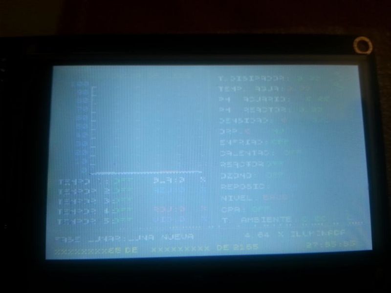
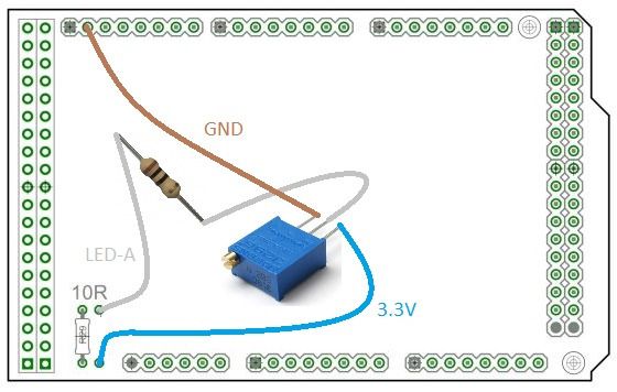
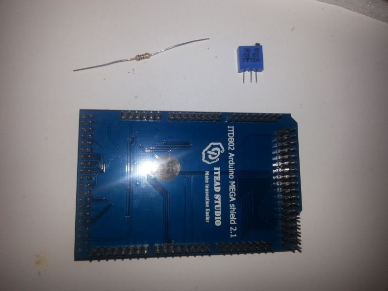
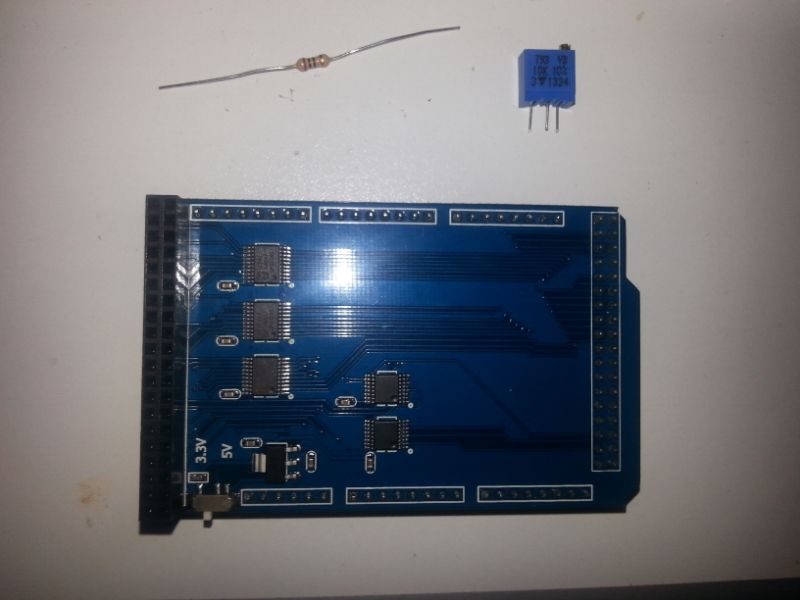
Since you ask in portalpez and you gave me a solution to the problem I had with my screen. I would fix it according to your instructions but I've noticed that your shield is different to mine and not know exactly where to weld. Could you help me?

Image


Image


Image


Image


Thanks!!!
Last edited by Fernando Garcia on Thu Jul 17, 2014 3:50 pm, edited 1 time in total.
Reason: Images fixed.

Post Number:#2 Post Thu Jul 17, 2014 3:52 pm
Posts: 1699
Topics: 38
Images: 301
Solve rating: 233
Joined: Mon Mar 03, 2014 5:59 pm
Topics: 38
Age: 39
Location: São Paulo
Gender: Male
National Flag:
Brazil

Hi!

Welcome Ismael!

You tried change the switch on TFT shield to 5V?

Best Regards.
Post your doubts on forum because it can help another user too. Just PM me for support if it's absolutely necessary.

Post Number:#3 Post Thu Jul 17, 2014 4:06 pm
Posts: 5
Topics: 1
Solve rating: 0
Joined: Thu Jul 17, 2014 2:54 pm
Topics: 1
Age: 43
Gender: None specified
National Flag:
Spain
Thanks Fernando


if you've tried and does not work

PD: I have another screen and sometimes when I turn the screen goes white, from left to right. I have to turn it on and off several times to function properly.

Post Number:#4 Post Thu Jul 17, 2014 4:30 pm
Posts: 1699
Topics: 38
Images: 301
Solve rating: 233
Joined: Mon Mar 03, 2014 5:59 pm
Topics: 38
Age: 39
Location: São Paulo
Gender: Male
National Flag:
Brazil

With the switch in 5V, check the voltage on pin "LED_A".

Image
Post your doubts on forum because it can help another user too. Just PM me for support if it's absolutely necessary.

Post Number:#5 Post Thu Jul 17, 2014 4:44 pm
Posts: 5
Topics: 1
Solve rating: 0
Joined: Thu Jul 17, 2014 2:54 pm
Topics: 1
Age: 43
Gender: None specified
National Flag:
Spain

Post Number:#6 Post Thu Jul 17, 2014 4:57 pm
Posts: 1699
Topics: 38
Images: 301
Solve rating: 233
Joined: Mon Mar 03, 2014 5:59 pm
Topics: 38
Age: 39
Location: São Paulo
Gender: Male
National Flag:
Brazil

3.89 is too, should be 3.25 more or less.

You can cut the trail that goes to this pin and put the potentiometer as shown in the image above.
Post your doubts on forum because it can help another user too. Just PM me for support if it's absolutely necessary.

Post Number:#7 Post Thu Jul 17, 2014 5:08 pm
Posts: 5
Topics: 1
Solve rating: 0
Joined: Thu Jul 17, 2014 2:54 pm
Topics: 1
Age: 43
Gender: None specified
National Flag:
Spain

Post Number:#8 Post Thu Jul 17, 2014 5:18 pm
Posts: 1699
Topics: 38
Images: 301
Solve rating: 233
Joined: Mon Mar 03, 2014 5:59 pm
Topics: 38
Age: 39
Location: São Paulo
Gender: Male
National Flag:
Brazil

I don't know.

I haven't this shield.

You need search.

The problem should be on shield because the voltage is high on LED_A.
Post your doubts on forum because it can help another user too. Just PM me for support if it's absolutely necessary.

Post Number:#9 Post Thu Jul 17, 2014 5:55 pm
Posts: 5
Topics: 1
Solve rating: 0
Joined: Thu Jul 17, 2014 2:54 pm
Topics: 1
Age: 43
Gender: None specified
National Flag:
Spain

Post Number:#10 Post Thu Jul 17, 2014 6:18 pm
Posts: 1699
Topics: 38
Images: 301
Solve rating: 233
Joined: Mon Mar 03, 2014 5:59 pm
Topics: 38
Age: 39
Location: São Paulo
Gender: Male
National Flag:
Brazil


Return to DIY Ferduino controller


Who is online

Users viewing this topic: No registered users and 1 guest

cron