General details:
See here the pin map of the board.
See here the name of the components

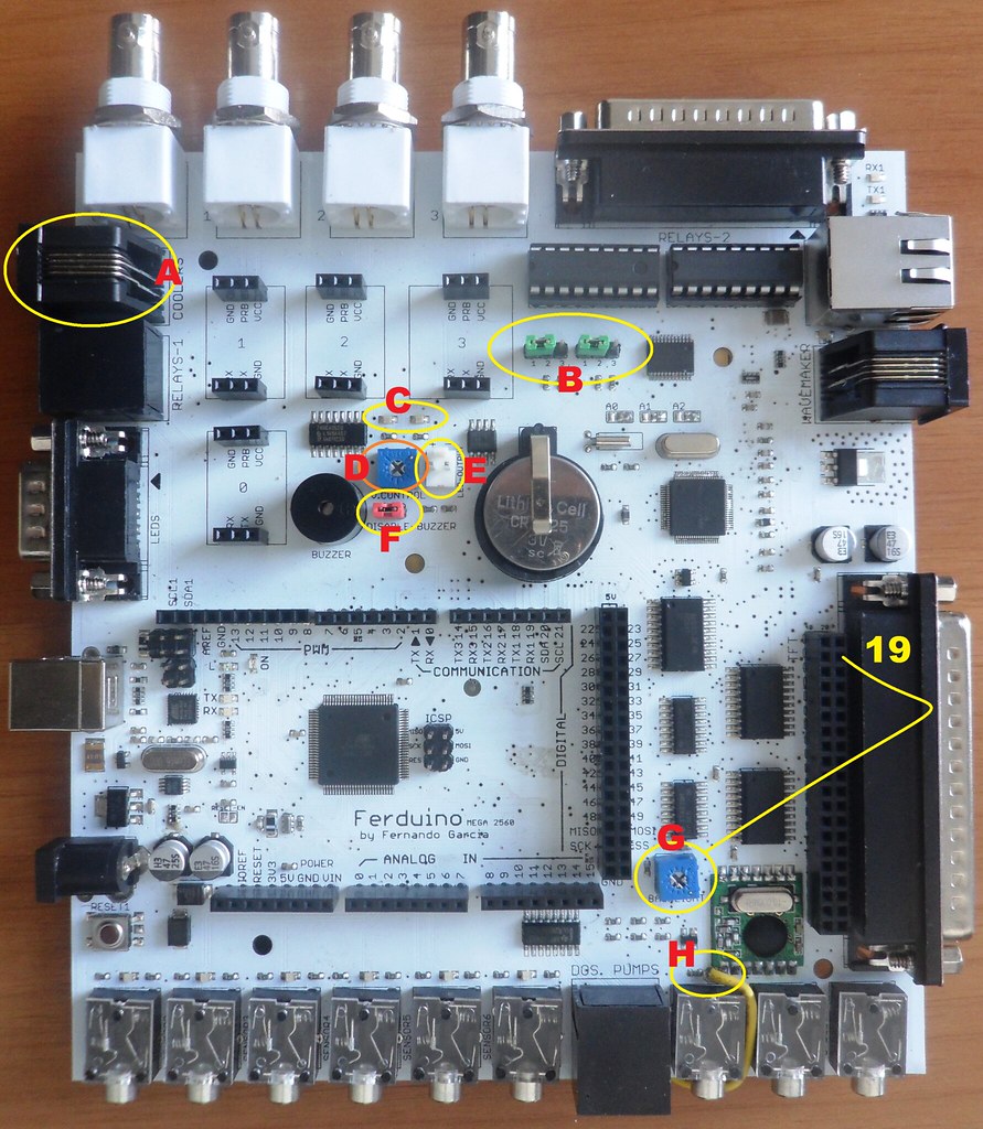
A - On connector is available the pin 1.
The pin 1 (TX) is used to serial communication, so remove any cable connected on this connector before of try send a code to the board.
To use the pin 1 as output remove all Serial.begin() of your code.
B - This jumpers are used to select pins for RTC.
To use the pins 18 and 19 put the jumper in the position 1-2.
To use the pins 20 and 21 put the jumper in the position 2-3.
Remember that to use Henning's library mandatorily the pins should be 18 and 19 therefore, position 1-2. No forget to set it on code.
C - This LED's are connected to pins 16 and 17 and in parallel with the multiplexer. This LED's allow see which channel is opened on multiplexer.
D - This trimmer allow control the volume of the buzzer.
E - This connector is connected to pin 0 and in parallel with the buzzer. Allow connect a small LED to be used as visual alarm.
The pin 0 (RX) is used to serial communication, so remove any cable connected on this connector before of try send a code to the board.
To use the pin 0 as output remove all Serial.begin() of your code.
F - This jumper allow disable the buzzer.
Remove this jumper before of try send a code to the board.
G - This trimmer allow control the brightness of the TFT.
Before of connect your TFT without a flat cable, check if have approximately 3.25 V on pin 19 shown in the image above. Otherwise adjust the trimmer.
H - Connect a small wire (antenna) on this place to use the module RF, following the length below.
1/4 wave = 77.9mm
1/2 wave = 155.9mm
Full wave = 327.8mm
Specific details:
By default the signal available on connector DB25 and controlled by PCF8575 is of 0 Volt, see a generic schematic below.
If you need of a signal of 5V, you can remove the ULN2803 and make bridges like this:
Check the datasheet to see the maximum output current for the PCF8575.
Wiring for dosing pumps:
Table pins:
TFT pinout:
The output in LED_A (backlight) is 0 - 3.3V controled for a trimmer.
TFT 800 x 480:
Warning: I'm not responsible for any problem. You do so at your own risk.
The TFT 800 x 480 have a pinout different as you can see below.
So some changes are needed.
First step:Remove the resistor shown below.
Second step: Make the wiring shown below:
Here the mode as Gianluca did.

More details soon.


