


Original price was: $220.00.$180.00Current price is: $180.00.
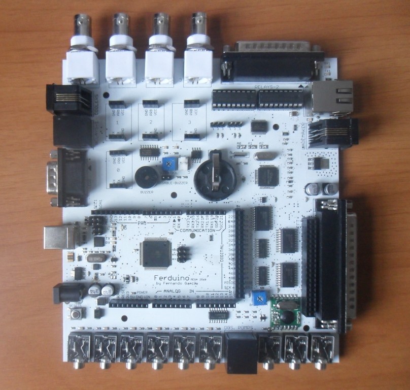
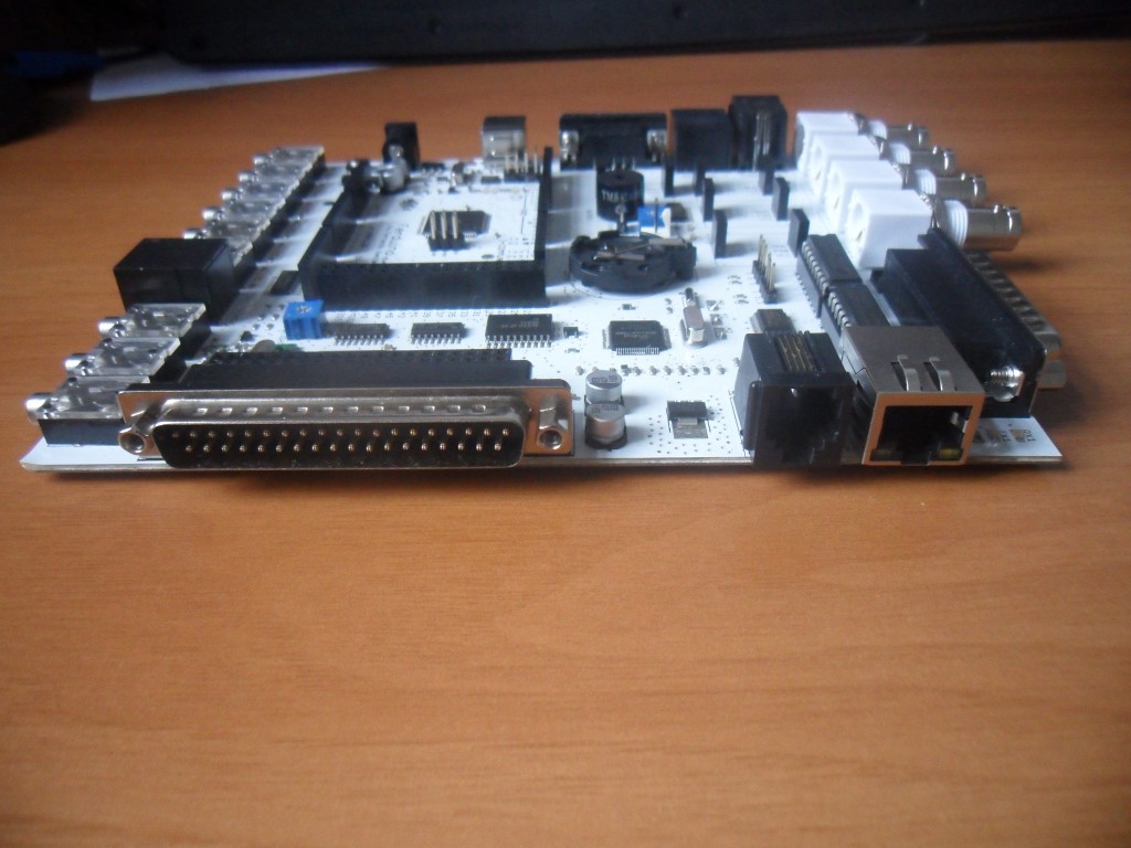
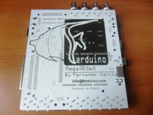
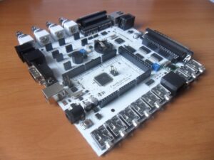
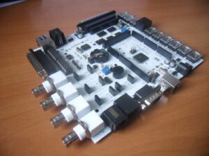
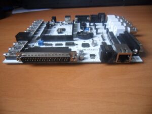
Ferduino Mega 2560 is a board Arduino compatible, that was done specially to work with Ferduino Aquarium Controller but, can be used with any project since that the pinout be respected.
Out of stock
Notify me when the item is back in stock.
Description
The Ferduino Mega 2560 is a board based on Arduino mega 2560 R3.
This board provide a microcontroller ATmega2560.
It has:
54 Digital input/output pins (of which 15 can be used as PWM outputs);
16 Analog inputs;
4 UARTs (hardware serial ports);
1 16 MHz crystal oscillator;
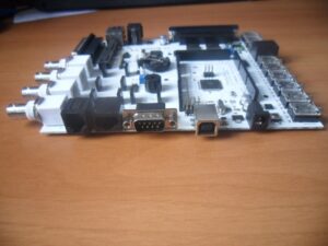
1 USB connection;
1 Power jack;
1 ICSP header;
1 Reset button.
This board provide still:
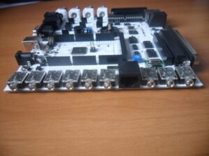
9 Jack phone 3.5 mm (6 are connected in analog pins and has pull up resistor of 10K and LEDs in parallel to be used with float switches, 3 are connected to a digital pin and has a resistor pull up of 4.7K Ohm to be used with temperature sensors in parasite mode);
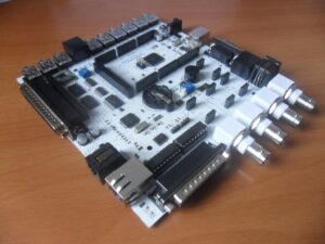
2 Jack RJ45 (1 connected in an ULN2003 that’s controlled by analog pins, this circuit allow control devices untill 50V / 500mA, 1 connected to 3 analog pins and 4 digital pins);
1 Header 2 x 20 connected to hex buffers that allow connect TFT’s of 3.3V directly;
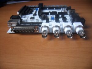
1 Connector DB37 in parallel with the header 2 x 20 that allow connect TFT’s of 3.3V using a serial cable;
2 Jack RJ11 (1 connected to digital pins, GND and 5V);
1 LAN;
1 Connector DB25 (connected to 2 ULN2803 controlled by an expander I2C)
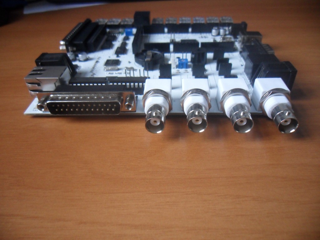
4 Connector BNC (connected to 4 sockets to be used with circuits from Atlas Scientific).
It contains everything needed to support the microcontroller; simply connect it to a computer with a USB cable or power it with a AC-to-DC adapter or battery to get started.
The Ferduino Mega 2560 is compatible with most shields designed for the Arduino Mega, Duemilanove or Diecimila.
Schematic: Ferduino Mega 2560
Names of components: Components – Ferduino Mega 2560
Pin mapping: PinMap
Summary
Microcontroller: ATmega2560;
Operating Voltage: 5V;
Input Voltage (recommended): 7-12V;
Input Voltage (limits): 6-20V;
Digital I/O Pins: 54 (of which 15 provide PWM output);
Analog Input Pins: 16;
DC Current per I/O Pin: 40 mA;
DC Current for 3.3V Pin: 50 mA;
Flash Memory: 256 KB (of which 8 KB used by bootloader);
SRAM: 8 KB;
EEPROM: 4 KB;
Clock Speed: 16 MHz.
Real Time Clock (with battery holder and jumpers to select the pins ’20, 21 or 18, 19′);
Ethernet controller;
Expander I2C with 16 I/O pins;
Multiplexer for 4 devices UART;
Buzzer for alarm (with trimpot to adjust of volume and jumper to disable);
Hex buffers for translation of voltage in logic level;
Wireless Transceiver of 915MHz.
Power
The Ferduino Mega can be powered via the USB (5V) connection or with an external power supply.
The power source is selected automatically.
External (non-USB) power can come either from an AC-to-DC adapter (wall-wart) or battery.
The adapter can be connected by plugging a 2.1mm center-positive plug into the board’s power jack. Leads from a battery can be inserted in the Gnd and Vin pin headers of the POWER connector.
If supplied with less than 7V, however, the 5V pin may supply less than five volts and the board may be unstable.
Using a voltage higher than 9V the cooling may be necessary (e.g. using a small fan), the heating causes a drop of voltage on circuits and destabilizes the operation of the board.
If using more than 12V, the voltage regulator may overheat and damage the board.
The power pins are as follows:
- VIN: The input voltage to the Ferduino board when it’s using an external power source (as opposed to 5 volts from the USB connection or other regulated power source). You can supply voltage through this pin, or, if supplying voltage via the power jack, access it through this pin.
- 5V: This pin outputs a regulated 5V from the regulator on the board. The board can be supplied directly on 5V or 3.3V pins but, this bypasses the regulator, and can damage your board. We don’t advise it.
- 3V3: A 3.3 volt supply generated by the on-board regulator. Maximum current draw is 50 mA.
- GND: Ground pins.
- IOREF: This pin on the Ferduino Mega provides the voltage reference with which the microcontroller operates. A properly configured shield can read the IOREF pin voltage and select the appropriate power source or enable voltage translators on the outputs for working with the 5V or 3.3V.
Memory
The ATmega2560 has 256 KB of flash memory for storing code (of which 8 KB is used for the bootloader), 8 KB of SRAM and 4 KB of EEPROM (which can be read and written with the EEPROM library).
Input and Output
Each of the 54 digital pins on the ATmega2560 can be used as an input or output, using pinMode(), digitalWrite(), and digitalRead() functions. They operate at 5 volts. Each pin can provide or receive a maximum of 40 mA and has an internal pull-up resistor (disconnected by default) of 20-50 kOhms. In addition, some pins have specialized functions:
- Serial: 0 (RX) and 1 (TX); Serial 1: 19 (RX) and 18 (TX); Serial 2: 17 (RX) and 16 (TX); Serial 3: 15 (RX) and 14 (TX). Used to receive (RX) and transmit (TX) TTL serial data. Pins 0 and 1 are also connected to the corresponding pins of the ATmega16U2 USB-to-TTL Serial chip.
- External Interrupts: 2 (interrupt 0), 3 (interrupt 1), 18 (interrupt 5), 19 (interrupt 4), 20 (interrupt 3), and 21 (interrupt 2). These pins can be configured to trigger an interrupt on a low value, a rising or falling edge, or a change in value. See the attachInterrupt() function for details.
- PWM: 2 to 13 and 44 to 46. Provide 8-bit PWM output with the analogWrite() function.
- SPI: 50 (MISO), 51 (MOSI), 52 (SCK). These pins support SPI communication using the SPI library.
- LED: 13. There is a built-in LED connected to digital pin 13. When the pin is HIGH value, the LED is ON, when the pins is LOW, it’s OFF.
- TWI: 20 (SDA) and 21 (SCL). Support TWI communication using the Wire library.
The ATmega2560 has 16 analog inputs, each of which provide 10 bits of resolution (i.e. 1024 different values). By default they measure from ground to 5 volts, though is it possible to change the upper end of their range using the AREF pin and analogReference() function.
There are a couple of other pins on the board:
- AREF: Reference voltage for the analog inputs. Used with analogReference().
- Reset: Bring this line LOW to reset the microcontroller. Typically used to add a reset button to shields which block the one on the board.
The Ferduino Mega provide an expander I2C that allow add 16 I/O pins to the controller. By default they are connected in an ULN2803 and should be used as OUTPUT but, is possible change removing the ULN and doing a bypass on pins.
Note: The pin INT isn’t connected.
The multiplexer allow connect up to 4 devices UART but 2 serial ports of the ATmega need be used. The pins are: 14 (TX), 15 (RX), 16 (S0) and 17 (S1). The pins 16 and 17 has LEDs in parallel to show which channel is being used.
Communication
The Ferduino Mega 2560 has a number of facilities for communicating with a computer or other microcontrollers. The ATmega2560 provides four hardware UARTs for TTL (5V) serial communication. An ATmega16U2 on the board channels one of these over USB and provides a virtual com port to software on the computer (Windows machines will need a .inf file, but OSX and Linux machines will recognize the board as a COM port automatically. The Arduino software includes a serial monitor which allows simple textual data to be sent to and from the board. The RX and TX LEDs on the board will flash when data is being transmitted via the ATmega16U2 chip and USB connection to the computer (but not for serial communication on pins 0 and 1).
The Wireless transceiver of 915 MHz enables the communication with other devices . The pins used are 50, 51, 52 (SPI), 69 (SS), 2 (INT).
The ethernet controller based on Wiznet W5100 chip provides a network (IP) stack capable of both TCP and UDP. It supports up to four simultaneous socket connections.
The board also includes a reset controller, to ensure that the W5100 Ethernet controller is properly reset on power-up.
The pins used are: 50, 51, 52 (SPI) and 53 (SS).
The board contains a number of informational LEDs:
- LINK: indicates the presence of a network link and flashes when the board transmits or receives data;
- 100M: indicates the presence of a 100 Mb/s network connection (as opposed to 10 Mb/s);
- RX1: flashes when the board receives data;
- TX1: flashes when the board sends data.
Note: The pin INT isn’t connected.
Storage
On connector DB37 and header 2 x 20 are available pins that allow use directly the SD card on board in some models of TFT.
The pins used are: 50, 51, 52 (SPI) and 5 (SS).
TFT touch interface
The Ferduino Mega provide an interface to the TFT’s more used actually.
The hex buffers are used to translate in logic level the voltage of the ATmega2560 (5V) to 3.3V. So the TFT can be connected directly.
Also has a trimpot of 10K that allow a small control over the backlight of the TFT.
The pins used are: 3 – 7 (touch) and 22 – 41 (TFT).
Programming
The Ferduino Mega can be programmed with the Arduino software. For details, see the reference and tutorials.
The ATmega2560 on Ferduino Mega comes preburned with a bootloader that allows you to upload new code to it without the use of an external hardware programmer.
USB Overcurrent Protection
The Ferduino Mega 2560 has a resettable polyfuse that protects your computer’s USB ports from shorts and overcurrent. Although most computers provide their own internal protection, the fuse provides an extra layer of protection. If more than 500 mA is applied to the USB port, the fuse will automatically break the connection until the short or overload is removed.
Package Contents
1 x Ferduino Mega 2560.
Notes:
Cables, TFT, battery, stamps and other accessories not included.
The buzzer is connected on pin 0, this pin is used in the serial port.
Then to make the upload of a code remove the jumper called “disable-buzzer”.
On connector RJ11 called “coolers” is available the pin 1 that’s too used in the serial port.
So remove any cable of this connector.
To use the buzzer and the pin 1 remove any function Serial.begin() of your code.
The buzzer has a connector called “led-output” in parallel that can be used with a LED as visual alarm.
Customs tax not included.
See here more details
Warranty and return
This board have warranty against defective materials or workmanship for 3 months from the date of original purchase. Proof of purchase is required. This warranty does not apply if, in the our judgemental, the board fails due to damage from shipment, handling, storage, accident, abuse or misuse, or if it has been used or maintained in a manner not conforming to product’s instructions or has been modified in any way.
If you are not fully satisfied with your board, we will accept a return and will credit the purchase price paid for the product (freight charges and return freight not included) if the board is free of obvious damage due to rough and/or improper handling within 30-days of purchase.
The product should be shipped to an address provided after authorization of return. Customers are responsible for the freight charges to Ferduino Aquarium Controller. We suggest using a carrier that provides tracking information. Ferduino Aquarium Controller isn’t responsible for packages lost in transit to us. The replacement product is shipped by ground with shipping charges prepaid. Expedited shipping is available at extra cost.
Shipment and payment:
Shipment from Brazil.
![]()
Additional information
| Weight | 250 g |
|---|---|
| Dimensions | 18.7 × 16.3 × 2.5 cm |